
- Catalogs
- BODINE ELECTRIC COMPANY
- Bodine Electric Handbook


- Company
- Products
- Catalogs
- News & Trends
- Exhibitions
Bodine Electric Handbook

Bodine Electric Handbook
This document provides a comprehensive overview of electric motors, focusing on the conversion of electrical energy into mechanical energy. It covers principles of electricity and magnetism, motor feedback, control systems, and mechanical principles governing motion.
Electric current is the movement of electric charge, measured in amperes, and can be direct (DC) or alternating (AC). Voltage measures electric pressure, and resistance opposes current flow. Ohm’s Law relates voltage, current, and resistance. Power is the rate of work done, calculated as P = VI.
Series circuits have total resistance as the sum of individual resistances, while parallel circuits have the same voltage drop across each branch.
A capacitor stores electric charge, with capacitance measured in farads. RC circuits include a resistor and capacitor, affecting charge and discharge rates.
Magnetism is essential for electric motors, with forces resulting from electric charges in motion. Magnetic fields exert forces without contact, and flux density measures field concentration.
Materials exhibit magnetic properties, with ferromagnetic elements like iron showing strong magnetic responses. Oersted discovered that electric current through a conductor creates a magnetic field.
A current-carrying conductor in a magnetic field experiences a force, the principle behind electric motors. Induced EMF occurs when a conductor cuts across magnetic flux lines.
AC generators induce alternating current by rotating a coil within a magnetic field, while DC generators use a commutator to maintain unidirectional current flow.
AC motors, particularly brushless induction types, operate on the principle of induction, where the stator's magnetic field induces currents in the rotor.
Various motor types include series motors, shunt-wound motors, permanent magnet motors, and brushless DC motors, each with unique advantages and limitations.
Designed for unique applications, such as fractional horsepower gearmotors and torque motors, offering specific performance characteristics.
Electric machines use magnetic fields to convert electrical energy into mechanical energy. Soft magnetic materials are ideal for motor cores, while hard materials are used as permanent magnets.
Bearings affect motor operation, with sleeve and ball bearings being common. Brushes, such as carbon and graphite types, require maintenance for optimal performance.
Insulation systems are rated by temperature, and motors are classified for environmental conditions, such as open or explosion-proof designs.
When selecting a gearmotor, consider gearing type, ratio, and application stresses. Proper lubrication and mounting are crucial for performance.
Motor controls regulate speed, torque, and position, with systems ranging from simple to complex. Feedback transducers and sensors are crucial for precise control.
Dynamic braking techniques vary for different motor types, with considerations for gearmotors and inertial loads.
Regular maintenance is essential for motor longevity, with guidelines for lubrication, brush maintenance, and environmental considerations.
Compliance with safety standards from organizations like ANSI and NEMA is crucial for safe motor operation. Proper installation and operation are essential to avoid hazards.
Catalog excerpts

For up-to-date product information, 2D/3D CAD drawings, or to order online, please visit www.bodine-electric.com 201 Northfield Road Northfield, Illinois 60093 U.S.A. Phone: 773.478.3515 | 800.7BODINE | Fax: 773.478.3232 www.bodine-electric.com | [email protected] Copyright Notice: Small Motor, Gearmotor and Control Handbook Copyright Bodine Electric Company. All rights reserved. Unauthorized duplication, distribution, or modification of this publication, in part or in whole, is expressly prohibited.
Open the catalog to page 1
Electric Motor Fundamentals Electric motors are designed to convert electrical energy into mechanical energy to perform some physical task or work. In order to understand the types of motors that are available as well as their performance characteristics, some understanding of the basic physical principles governing motor design and operation are required. Basic electric motor design encompasses the laws of electricity and magnetism. Motor feedback and control systems involve semiconductor devices, microprocessors and other elements of electronics. And no discussion of motors would be complete...
Open the catalog to page 2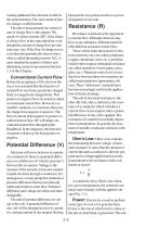
causing additional free electrons to drift in the same direction. This movement of electric charge is called current. The unit of measurement for current or rate of charge flow is the ampere. We speak of a direct current (DC) if the charges always flow in the same direction, even though the amount of charge flow per unit time may vary. If the flow of charge reverses its direction periodically, then we have what is called alternating current (AC). A more detailed description of direct and alternating current is presented in Section 1.3 of this Chapter. Conventional Current Flow: Before the acceptance...
Open the catalog to page 3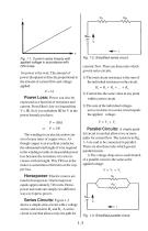
Fig. 1-2: Simplified series circuit. Fig. 1-1: Current varies linearly with applied voltage in accordance with Ohm’s law. for power is the watt. The amount of power dissipated is directly proportional to the amount of current flow and voltage applied: P = VI curremt flow. There are three rules which govern series circuits. 1) The total circuit resistance is the sum of the individual resistances in the circuit: RT = R1 + R2 + ... + RN Power Loss: Power can also be 2) Current has the same value at any point within a series circuit. expressed as a function of resistance and current. From Ohm’s law...
Open the catalog to page 4
2) The total current in a parallel circuit is equal to the sum of the branch currents: I = I 1 + I2 where I1 and I2 are currents flowingpart of through R1 and R2 respectively. 3) The total resistance in a parallel circuit is always less than or approximately equal to the value of the smallest resistance in any branch of the circuit. Since I = I1 + I2 you can substitute V -- in place of I and arrive at: R V V V -- = --1 + --2 RT R1 R2 Q, measured in coulombs, is the charge stored in the capacitor. One coulomb has an equivalent charge of about 6.24 x 10¹⁸ electrons. The unit of capacitance (C)...
Open the catalog to page 5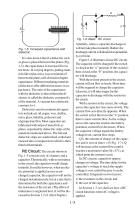
Fig. 1-5: Increased capacitance with dielectric. It is also known that if a dielectric such as glass is placed between the plates (Fig. 1-5), the capacitance is increased five to ten times. In varying degrees, putting materials like mylar, mica, wax or mineral oil between the plates will all result in higher capacitance. Different insulating materials (dielectrics) offer different increases in capacitance. The ratio of the capacitance with the dielectric to that without the dielectric is called the dielectric constant (k) of the material. A vacuum has a dielectric constant: k=1. Dielectrics used...
Open the catalog to page 6
Fig. 1-7: Curves for Q and I during charging. Fig. 1-8: Curves for Q and I during discharging. Time Constant: The time it takes a capacitor to charge to 63% of the supply voltage is called the capacitive time constant (T). It can be calculated using the formula: T = RC A capacitor discharges in a similar manner as shown in Fig. 1-8. The current is now negative, because it flows in the opposite direction during discharging. A capacitor is said to be fully charged or fully discharged after five RC time constants. The figures illustrate that current varies exponentially with time during the charging...
Open the catalog to page 7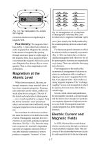
Fig. 1-9: Flux field pattern of a simple bar magnet. Fig 10: Arrangement of: a) electrons in diamagnetic materials (left), and b) electrons in magnetic materials (right). exerted on electrons moving through a magnetic field. Flux Density: The magnetic field lines in Fig. 1-9 are collectively referred to as the magnetic flux. Magnetic flux density is the amount of magnetic flux passing through a unit area plane at a right angle to the magnetic field. It is a measure of how concentrated the magnetic field is in a given area. Magnetic flux density (B) is a vector quantity. That is, it has magnitude...
Open the catalog to page 8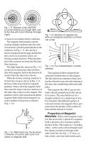
Fig. 1-11: Direction of flux flow with a) current flowing out of page (left), and b) flux flow with current flowing into page (right). of most of our modern electric machines. The magnetic field around a currentcarrying straight conductor takes the form of concentric cylinders perpendicular to the conductor. In Fig. 1-11, the current is shown emerging from the page and the flux lines, shown as concentric circles, are flowing counterclockwise. When the direction of the current is reversed, the flux lines flow clockwise. The right-hand rule, shown in Fig. 1-12, can be used to determine either the...
Open the catalog to page 9
Fig. 1-15: Effect of an iron bar on a magnetic field. variety of other ferromagnetic alloys and compounds are excellent magnetic conductors with high permeability. Permeability and Magnetic Field Strength: Permeability (µ) is a measure of how well a material will conduct magnetic flux. It is related to magnetic flux density (B) and magnetic field strength (H) in the following equations: and where µo = 4π x 10-7 (in SI units) and µr is the relative permeability with a value of unity (1) in free space. The magnetic field strength (H) is measured in amperes per meter. The following formula shows...
Open the catalog to page 10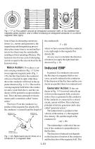
Fig. 1-17: a) Flux pattern around an energized conductor (left), b) flux between two magnetic poles (center), and c) effect of placing an energized conductor in a uniform magnetic field (right). form of heat. In alternating current machines (i.e., motors and generators), the magnetizing and demagnetizing process takes place many times a second and hysteresis loss (heat) may be considerable, resulting in lower operating efficiency. The hysteresis loss for one cycle of alternating current is equal to the area enclosed by the hysteresis loop. Motor Action: If we place a current-carrying conductor...
Open the catalog to page 11All BODINE ELECTRIC COMPANY catalogs and technical brochures
 STANDARD PRODUCTS 2025
52 Pages

Archived catalogs
 PLANETARY BLDC GEARMOTORS
2 Pages
 IP-69K
2 Pages
 IP-66
IP-662 Pages
 42R-5L/H
2 Pages
 33A7-WX
2 Pages
 34B-WX , 33A-WX
2 Pages
 42R-FX AC Gearmotor
2 Pages
 2998
29982 Pages
 STANDARD PRODUCTS 2024
52 Pages






- Synchronous motor
- Multipole motor
- Bodine Electric gear-motor
- EC motor
- Electromotor for industrial applications
- 24 V motor
- Bodine Electric DC gear-motor
- 4-pole motor
- Compact electromotor
- Industrial electric gearmotor
- Bodine Electric right angle gear-motor
- Bodine Electric AC gear-motor
- Motor controller
- Bodine Electric 24 V gear-motor
- Solid-shaft gear-motor
- Bodine Electric gear train gear-motor
- Planetary gearmotor