
- Catalogs
- BODINE ELECTRIC COMPANY
- Bodine Electric Company Type 34R6BXPP Motors & Gearmotors


- Company
- Products
- Catalogs
- News & Trends
- Exhibitions
Bodine Electric Company Type 34R6BXPP Motors & Gearmotors
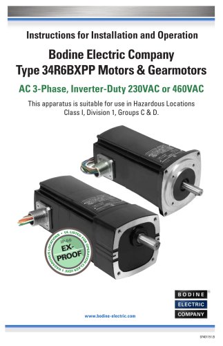
Bodine Electric Company Type 34R6BXPP Motors & Gearmotors
This section highlights the potential hazards of using electric machines in hazardous locations. It stresses the importance of proper design, selection, installation, and use to mitigate risks. The Bodine type 34R6BXPP motor and gearmotor comply with UL and CSA standards for hazardous locations. Users are advised to disconnect equipment from the power supply before opening and ensure the assembly remains tightly closed during operation. Installation and maintenance should be performed by qualified electricians.
The 34R6BXPP motors are 3-Phase AC induction motors suitable for hazardous (Class I, Division 1, Groups C & D) and non-hazardous locations. They operate at 230 VAC or 460 VAC with a frequency range of 10-120 Hz for motors and 10-90 Hz for gearmotors. The motors have a temperature code of T4A or T3C and are rated for ambient temperatures from -20°C to 40°C. Detailed specifications for different gear ratios, including speed, torque, and speed range, are provided.
Installation should be conducted by a qualified person familiar with the product's operation and hazards. The National Electrical Code and other relevant safety codes must be observed. Detailed instructions for mounting the motor or gearmotor, including appropriate hardware and dimensions for standard models, are provided. A conduit outlet box for hazardous locations, which must be purchased separately, is required.
The motors require a 3-phase AC voltage source or a suitable controller. The document outlines the need for a logic input, electronic overload protection, or a relay circuit to prevent the motor from exceeding temperature ratings. Schematic representations of recommended electrical connections are provided.
This section assists users in diagnosing and resolving common issues during the operation of the motor or gearmotor.
The document concludes with information about the limited warranty provided by Bodine Electric Company, covering the terms and conditions under which the warranty applies.
Detailed instructions on electric connections for the 34R6BXPP Motor or Gearmotor in a Class I, Division 1 environment are provided. Diagrams illustrate connections for thermal switches with AC relays, logic control, and 3-pole AC relays. Key points include:
- Thermal switches must interrupt power to limit motor temperature.
- Contact ratings for thermal switches are specified for both AC and DC.
- Warnings about automatic motor restart if allowed by control logic.
Steps for operating the motor or gearmotor include:
- Ensuring secure mounting and alignment of the gearmotor.
- Starting and stopping procedures for the motor with or without an inverter.
- Adjusting speed using an inverter.
If issues arise, users are advised to:
- Double-check wiring and installation.
- Contact Bodine Authorized Service Centers for persistent problems.
- Avoid unauthorized repairs to maintain warranty validity.
Bodine Electric Company offers a warranty covering defects in workmanship and materials under normal operating conditions. Key points include:
- A 24-month warranty for products used with Bodine controls, and a 12-month warranty for others.
- Repair, replacement, or refund options for defective products within the warranty period.
- Exclusions for consequential damages and normal wear and tear.
Bodine offers a wide selection of variable-speed motors and gearmotors. For more details, specifications, and ordering, visit their website.
Catalog excerpts
Instructions for Installation and Operation Bodine Electric Company Type 34R6BXPP Motors & Gearmotors AC 3-Phase, Inverter-Duty 230VAC or 460VAC This apparatus is suitable for use in Hazardous Locations Class I, Division 1, Groups C & D. www.bodine-electric.com www.bodine-electric.com
Open the catalog to page 1
This manual contains the basic information needed to install and operate a Bodine type 34R6BXPP three-phase AC motor or gearmotor that is certified for use in Class I Division 1 hazardous locations. This manual does not profess to cover all details or variations in equipment, nor to provide for every possible contingency associated with installation, operation, or maintenance. No warranty of fitness for purpose is expressed or implied. It is the responsibility of the user to determine whether the installation location is hazardous, and to what degree it is hazardous. Should further information...
Open the catalog to page 2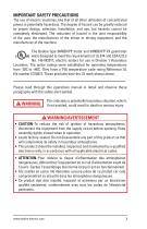
IMPORTANT SAFETY PRECAUTIONS The use of electric machines, like that of all other utilization of concentrated power, is potentially hazardous. The degree of hazard can be greatly reduced by proper design, selection, installation, and use, but hazards cannot be completely eliminated. The reduction of hazard is the joint responsibility of the user, the manufacturer of the driven or driving equipment, and the manufacturer of the machine. The Bodine type 34R6BXPP motor and 34R6BXPP-FX gearmotor were designed to meet the requirements of UL 674 and CSA C22.2 No. 145-M2017, electric motors for use in...
Open the catalog to page 3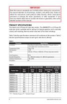
Read this manual completely and carefully before making any connections. Pay special attention to all warnings, cautions, and safety rules. Failure to follow the instructions could produce safety hazards, which could injure personnel or damage the motor, gearmotor, or other equipment. If you have any doubts about how to connect the motor or gearmotor, refer to the detailed sections of this manual.. The motors are 3-Phase AC induction motors. The 34R6BXPP is a 3-Phase AC induction motor, available with or without an integral gearbox, and a normally closed, self-resetting thermal switch attached...
Open the catalog to page 4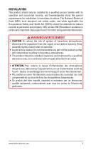
This product should only be installed by a qualified person familiar with its operation and associated hazards, and knowledgeable about the special requirements for installation in hazardous locations. The National Electrical Code (NEC), local electrical and safety codes, and when applicable, the Occupational Safety and Health Act (OSHA) should be observed to reduce hazards to personnel and property. NEC section 500 (Hazardous Locations) is particularly important. See pages 6 and 7 for motor and gearmotor dimensions. ! • CAUTION–To reduce the risk of ignition of hazardous atmospheres, disconnect...
Open the catalog to page 5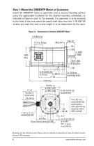
Step 1: Mount the 34R6BXPP Motor or Gearmotor Install the 34R6BXPP motor or gearmotor onto a secure mounting surface using the appropriate hardware for the desired mounting orientation, as indicated in Figure 1a and 1b. For example, if a gearmotor is to be mounted by the holes in the face where the output shaft exits, then four ¼-28 UNF‑2B screws are used (the max screw length is to be determined by the user). Figure 1a – Dimensions for Standard 34R6BXPP Motor 2x .39 Base mounting holes 17 / 18 Number of leads varies 2x .39 Base mounting holes 1” NPT x 11-1/2 threads per inch 4.01 Max. Base mounting...
Open the catalog to page 6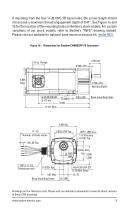
If mounting from the four ¼-20 UNC-2B base holes, the screw length should not exceed a maximum thread engagement depth of 0.47”. See Figure 1a and 1b for the location of the mounting holes on Bodine’s stock models. For custom variations of our stock models, refer to Bodine’s “INFS” drawing instead. Please visit our website for optional base mount accessory kit, model 0931. Figure 1b – Dimensions for Standard 34R6BXPP-FX Gearmotor Base mounting holes 4.640 Sq 17 / 18 Number of leads varies unting holes 4.01 Max Base mounting holes Drawings are for reference only. Please visit our website to download...
Open the catalog to page 7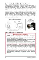
Step 2: Attach a Conduit Outlet Box to the Motor Proper installation of this product in a hazardous location requires the use of a conduit outlet box listed for Class I, Division 1, Groups C & D. The conduit outlet box is not supplied by Bodine with the motor, so it must be purchased separately by the user. The conduit outlet box must have a hole with a 1” NPT, 11.5 threads per inch female thread in order to fit onto the Bodine motor. A minimum of 5 threads of engagement is required to meet the UL 674 standard. This conduit outlet box should be sized per NEC 314.16. Figure 2 shows one example...
Open the catalog to page 8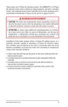
These motors are 3-Phase AC induction motors. The 34R6BXPP is a 3-Phase AC induction motor, with or without an integral gearbox, and with a normally closed, self-resetting thermal switch attached to the motor windings and is represented schematically in Figures 4a, 4b, and 4c on pages 10 and 11. • CAUTION-The motor may automatically restart, depending on how it is wired to the power source, after the temperature has cooled sufficiently to allow the protector contacts to reset and if AC power is present. • ATTENTION-Le moteur peut redemarrer automatiquement, en fonction de la fagon dont il est...
Open the catalog to page 9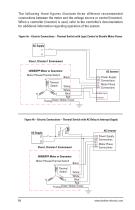
The following three figures illustrate three different recommended connections between the motor and the voltage source or control (inverter). When a controller (inverter) is used, refer to the controller’s documentation for additional information regarding operation of the system. Figure 4a – Electric Connections – Thermal Switch with Logic Control to Disable Motor Power AC Supply L1 L2 Class I, Division 1 Environment 34R6BXPP Motor or Gearmotor Motor Phases/Thermal Switch U Thermal Switch White White Blue V Red Frame Green-Yellow Tracer Power Supply Connections Motor Phase Connections Enable...
Open the catalog to page 10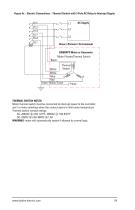
Figure 4c – Electric Connections – Thermal Switch with 3 Pole AC Relay to Interrupt Supply (N.O.) Class I, Division 1 Environment 34R6BXPP Motor or Gearmotor Motor Phases/Thermal Switch Black Thermal Switch White White Blue V Red Green-Yellow Tracer THERMAL SWITCH NOTES: Motor thermal switch must be connected to interrupt power to the controller and / or motor windings when the contact opens to limit motor temperature. Thermal switch contact ratings: AC–250VAC @ 2.5A 1.0 P.F., 250VAC @ 1.6A 0.6 P.F. DC–24VDC @ 3.5A 48VDC @ 1.5A WARNING: motor will automatically restart if allowed by control logic....
Open the catalog to page 11All BODINE ELECTRIC COMPANY catalogs and technical brochures
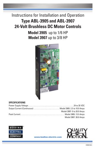 Type ABL-3905 and ABL-3907
24 Pages
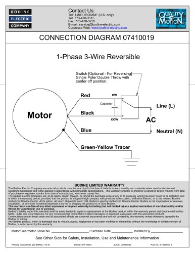 1-Phase 3-Wire Reversible
2 Pages
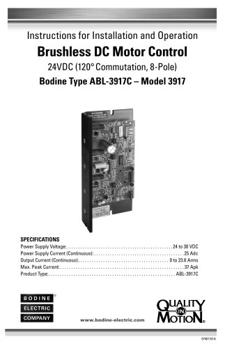 Brushless DC Motor Control
24 Pages
 Type ABL-3906C Low-Voltage
20 Pages
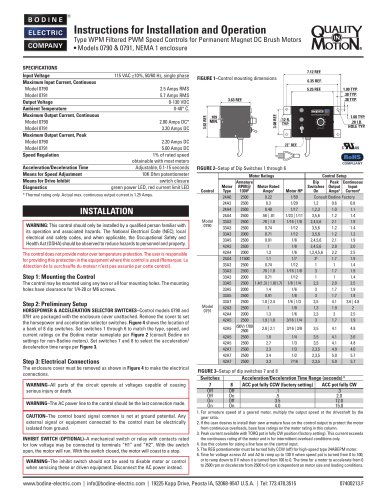 Models 0790 & 079
2 Pages
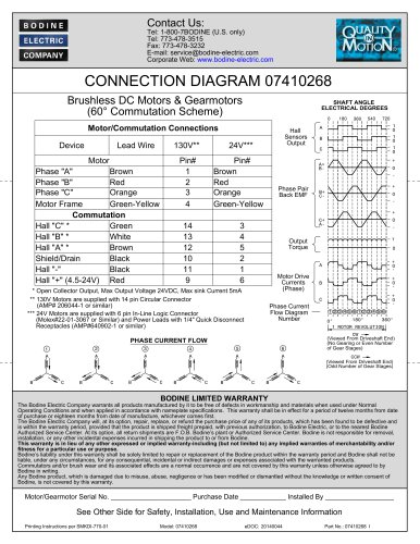 CONNECTION DIAGRAM 07410268
2 Pages
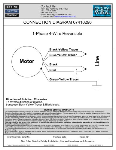 1-Phase 4-Wire Reversible
2 Pages
 STANDARD PRODUCTS 2025
52 Pages
 Bodine Electric Handbook
252 Pages
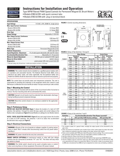

Archived catalogs
 PLANETARY BLDC GEARMOTORS
2 Pages
 IP-69K
2 Pages
 IP-66
2 Pages
 42R-5L/H
2 Pages
 33A7-WX
2 Pages
 34B-WX , 33A-WX
2 Pages
 42R-FX AC Gearmotor
2 Pages
 2998
2 Pages
 STANDARD PRODUCTS 2024
52 Pages






- DC electromotor
- Synchronous motor
- Bodine Electric gear-motor
- Electromotor for industrial applications
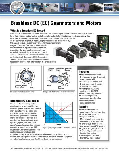
- EC motor
- Bodine Electric DC gear-motor
- Compact electromotor
- Permanent magnet motor
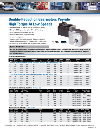
- Bodine Electric AC gear-motor
- Industrial electric gearmotor
- Bodine Electric right angle gear-motor
- Motor controller
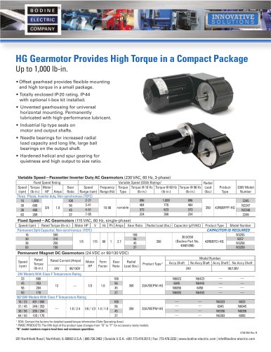
- Bodine Electric 24 V gear-motor
- Bodine Electric gear train gear-motor
- Planetary gearmotor
- Bodine Electric compact gear-motor
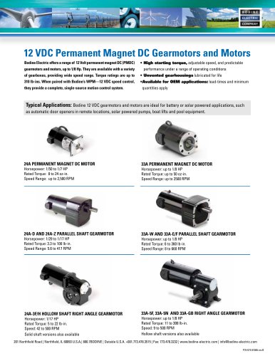
- 12 V electric gearmotor
- Bodine Electric low-noise gear-motor
- Bodine Electric parallel-shaft gear-motor