SFU 0401
1 /10Pages

SFU 0401
1 /10Pages
Catalog excerpts
STATIC FREQUENCY CONVERTER ♦ microcontroller: ♦ mains voltage: ♦ protection: ♦ max. power consumption: ♦ max. spindle shaft output (1): ♦ output voltage: ♦ maximum output current:: ♦ frequency range: Technical Data supervision, controlling and closed-loopcontrol 230 V AC 50 / 60 Hz 2 x T 15 A / 250 V 2,6 K VA / Version P : 3,6 K VA 3 x 0 ... 220 V I max. 8 A / Version P : 11,5 A 83...1.000 Hz * 5000...60.000 rpm Other frequencies are programmable by software (max.2.000 Hz 120.000 rpm) ♦ the 3 phases are short-circuit protected by an electronic current limitation ♦ programming and remote-controlling by a serial interface (RS 232) ♦ field bus-interface (interbus-S or profibus) is in development ♦ the characteristic data of the spindle are able to individually set parameter values, thus usable for different spindles of different spindle producers (by BMR set parameter values) ♦ characteristic-curves are able to be stored in Data-files. (BMR takes in the characteristics of the spindles) ♦ re-check of spindle-standstill after power-up the supply voltage; if needed electronic brake till standstill of spindle. The re-check of spindle-standstill works also with spindles without a magnetoresistor ♦ automatically detection of cable-disruption for the 3 phases of the spindle after power-up of the supply-voltage ♦ fulfilment of all electromagnetic prescriptions within industrial area
Open the catalog to page 1
O superheat spindle O O spindle not ready for operation START O rotational speed reached — O standstill of spindle O superheat converter Q — O converter not ready for operatiorSTOP O overload converter — front view of control cubicle configuration 1. manufacturers emblem 2. display for converter 3. display for spindle 4. display spindle „OFF“ 5. press button spindle „OFF“ 6. load display (load of spindle in %) 7. press button spindle „ON“ 8. display spindle „ON“ 9. adjustment for rotational speed 10. digital display of rotational speed, respectively different error messages 13....
Open the catalog to page 2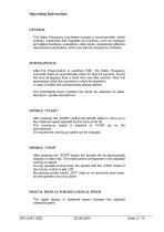
Operating Instructions GENERAL This Static Frequency Converters includes a microcontroller, which controls, supervises and regulates all functions, such as analogue and digital interfaces, evaluations, data inputs, respectively effective transmission-parameters; which can also be changed by software. POWER SWITCH After the Power-button is switched "ON"; the Static Frequency Converter starts an automatically check for about 8 seconds. During this time all displays flash a short time one after another. After this automatical check the converter is ready for operation. In case of defect the corresponding...
Open the catalog to page 3
LED „red“ LED „red“ LED „red“ LED „green“ converter superheat converter is not ready for operation load of converter or load of spindle higher than 100% remote control „ON“ LED „red“ LED „red“ LED „green“ LED „green“ spindle superheat spindle is not ready for operation rotational speed reaches „desired value“ or „actual value“, respectively" standstill of spindle ERROR MESSAGES (seven-segment display) = cable disruption phase 1 = cable disruption phase 2 = cable disruption phase 3 = no spindle = final stage powered down due overcurrent
Open the catalog to page 4
LOAD DISPLAY The load display indicates the present load of spindle in %. If the spindle is not loaded and no defect exists, the load-display indicates approx. „0%“. OVERLOAD DISPLAY The display (7) always flashes, when the spindle was overloaded or the interruption for overload responded. OVERLOAD POWER CUT If the spindle is running more than 10 seconds [programmable by software (1...10 sec.)] in overload an interruption for overload will follow. I.e. after this time the converter automatically disconnects the spindle and the displays (6) and (7) are flashing. Another „power-up“ of the spindle...
Open the catalog to page 5
EXCESS TEMPERATURE OF SPINDLE When the spindle reached the excess temperature the display (1) flashes. Delayed with 3 seconds. [programmable by software (1...10 sec.)] the converter switches to „STOP“ and the display (2) flashes. The spindle cannot be switched „ON“ before the display (2) disappeared. The display (1) disappears by another „power-up“. ATTENTION: This evaluation is only possible if the spindle is equipped with a temperature sensor. (Option after arrangements) REMOTE CONTROL The remote control of the converter is connected via the 15-poles SUB-D-JACK (13) The display (8) flashes...
Open the catalog to page 6
ROTATIONAL SPEED REACHED If the spindle reached the preset rotational speed, the display (3) flashes. The converter considers two possibilities of the evaluation: a; b; when the spindle is not equipped with a magnetoresistor, the symbol flashes if the internal frequency of the converter corresponds to the adjusted frequency. when the spindle is equipped with a magnetoresistor the symbol flashes only if the spindle axle reached the adjusted rotational-speed in fact (actual evaluation). Attention: This is only possible if the spindle is equipped with a magnetoresistor The display (4) flashes whenever...
Open the catalog to page 7
CONFIGURATION ^ ACTIVE LOAD OUTPUT With the control connector (13) pin 4 (+) and pin 8 (A) ground, a direct voltage is given out which corresponds to the load of the spindle. 0...12 V £ 0...120% INFORMATION: Standard for delivery is the configuration „rotational speed output"! EMERGENCY SHUTDOWN INTERLOCK The emergency shutdown interlock can be programmed by software to „active“ or „inactive“. Programming „inactive“ is insignificant, whereas with a „active“ programming a primary stop-command can be given. This means that the converter cannot be started again neither by the „Start-button“ nor...
Open the catalog to page 8All BMR GmbH catalogs and technical brochures
 Catalogue
52 Pages
 SFU 0102
28 Pages
 SFU 400
15 Pages
 SFU 0102/0202
28 Pages
 SFU 0103/0203
30 Pages
 SFU 0303
56 Pages
 SFU0300
24 Pages
 SFU-ErrorFlags
7 Pages
 RS232 Control Commands
6 Pages
 SpindlecoolerKG-T 500
24 Pages
 DressView
32 Pages
 Folnet P S / P S 300
8 Pages
 Folnet P
8 Pages
 Folnet3-NT
8 Pages
 Folnet 1 NT
8 Pages
 Folnet 1
8 Pages
 Folinv 12/3
4 Pages
 SFU 0302 19”
28 Pages
 SFU 0302 SSE
30 Pages
 SFU 0101/0201
17 Pages
 SFU 0100
2 Pages
 SFU 0303/4
48 Pages
 SFU 0303/2
50 Pages
 SFU0052
12 Pages
 SFU 0200/1
24 Pages
 SFU 0103
24 Pages
 SFU 0156
20 Pages
 SFU 0150
20 Pages
 KG-T 500
20 Pages

- Measuring machine
- Automatic measurement system
- Frequency inverter
- Measuring system for industrial applications
- Compact frequency inverter
- Digital output frequency inverter
- Motor frequency converter
- IP20 frequency inverter
- Vector control frequency inverter
- LED driver
- Integration frequency inverter
- Fieldbus frequency inverter
- Induction frequency converter
- Cabinet frequency inverter
- Low-voltage frequency inverter
- Asynchronous motor frequency inverter
- Vector-controlled frequency inverter
- Digital display frequency inverter
- Synchronous motor frequency inverter
- PROFIBUS frequency inverter