SFU 0303
1 /56Pages

SFU 0303
1 /56Pages
Catalog excerpts
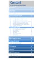
Front panel of SSE, Desktop und 19“ Version Basics and Preconditions for Operation Status LED Display LCD‐Operating Panel Start / Stopp Setup of Rotational Speed Safety Functions Safe Power Stage Pulse Lock Mains and Spindle Connection Logic and Wiring for Safety
Open the catalog to page 3
1. Introduction Due to its construction, the rotational speed of a 3‐phase Asynchronous‐AC‐Motor is directly dependent on the frequency of the voltage and the number of poles. In case of a 3PH 50Hz voltage and a 2‐pole motor, the nominal speed would be 50 rps * 60 = 3000 rpm. In case of Synchronous‐BLDC motors (brushless dc), the speed is directly dependent on the voltage applied. 3‐phase AC motors provide numerous benefits in industry, such as brushless operation, freedom from wear and tear, favorable capacity/weight ratio, high‐speed capability, and ...
Open the catalog to page 4
Operating panel is detachable and can be used as remote control together with an extension cable. Cloning capability of the whole project setup with the help of the Operating Panel Designed for roughest use in industrial environment Specific construction of the SSE‐housing realized without ventilations slots and an outside mounted heatsink prevents intrusion of dirt and chips of tooling into the control unit. Very compact case style makes easy cabinet mounting possible Several case options for cabinet mounting (SSE) , 19" rack style and desktop, or special designs ...
Open the catalog to page 5
High operational safety: All operating conditions like acceleration, operation with nominal rotational speed, deceleration is monitored and critical conditions are intercepted.
Open the catalog to page 6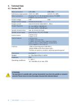
Output‐current Output frequency
Open the catalog to page 8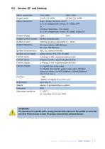
4.2 Version 19" und Desktop Mains connection 115V, 60Hz 230V, 50Hz Output power 2 kVA / S1‐100% 3,6 kVA / S1‐100% Motor connection 9‐pin: Screw Terminals 4mm² U, V, W, temperature sensor, FP, SGND 2xPE or Circular Connectors 7 or 13‐pin: U, V, W, temperature sensor, FP, SGND, Shield, PE Output voltage 110V 220V Output current / power...
Open the catalog to page 9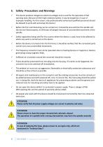
This device produces dangerous electrical voltages and is used for the operation of fast spinning tools. Because of their high rotational speed, it may be dangerous in case of improper handling. For this reason, only professionally trained and qualified personnel should be allowed to work with and setup this device! Before the first commissioning can be carried out, it should be ensured that the spindle and the tool are fixed properly, to eliminate all dangers because of uncontrolled movement of the spindle. All repairs and maintenance on the converter and the relating accessories must be carried out ...
Open the catalog to page 10
For embedding into PLC and controls the SFU0303 has several input and outputs. They are realized as pluggable screw terminals and are located at the front or rear panel (depending on case option). All contacts are separated galvanically from high voltage carrying circuits. Operational parameters and outputs: The SFU‐0303 captures all current important operational parameters and operating data. Up to 6 digital outputs can be used for signaling and up to 2 analogue values can be output to the analogue outputs (0‐10V) . Remote Control and Outputs: 6 digital inputs (24V) and 2 analogue inputs (0‐10V) are available for remote control of the ...
Open the catalog to page 11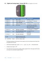
S Analogue input range: 0.10V S The +24V at Pin 10 can be used as auxiliary voltage supply for Start / Stop signal with the help of a relay or for an electronic spindle interface.
Open the catalog to page 12
11 Analog Out 2 Output 12 Hall Sensor‐Output Output modified signal square shape signal from encoder The Reference‐Ground for digital and analog signals: Clamp terminal X2.9 The Default‐settings of the functions for the outputs can be set up freely with the help of the PC‐Software SFU‐Terminal. An exception is the signal "Power Stage Pulse Lock", which is linked fix with Relay 6. According to the switch state it will be output 0V / GND or +24V via 10kΩ referring to GND (X2.9) (‐> 8.2 / 8.7) +24V: Output Power Stage released 0V: Output Power Stage locked. Relay Output: ...
Open the catalog to page 13
2) With SFU-Terminal the "active" function of the relays can be changed to "not energized " also. By this an inversion is achieved, with the restriction that this is applied to the inverter during operation at POWER-ON, only, because it is just realized by software. At POWER-OFF, the relay contacts have the default setting as in 1 ) S The digital outputs (Relay1...5) are galvanically separated (500VIsolation). DC: 24V / 1000mA AC: 125V / 500mA S Output level Speed / Hall Sensor: 0-24V (24V Level) 6.3 Spindle Interface X4 (9 pin Pluggable screw terminal) The Default-settings of the functions for...
Open the catalog to page 14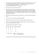
The spindle interface is separated with optocouplers from all other signals. It can be used for an automatic spindle detection, if activated. The logic levels are low‐active by default: "HI" > PIN connected with Spindle‐GND, "LO"‐ > PIN unwired In the menu "Digital Inputs" this can be changed. GND signal X4 is electrically isolated from GND X2 The temperature sensor input is provided to detect overtemperature on the spindle. With linear temperature sensors (KTY, PT1000), the switching thresholds for the error messages "Spindle overtemperature" can be freely defined using the SFU terminal. If PTC is selected, it ...
Open the catalog to page 15
View at screw terminals at version SSE: The device has no internal fusing. It has to be fused externally Please ensure, that PE protective earth is connected at the mains side. The device must not be operated without properly connected PE! A Please ensure, that PE protective earth is connected at the spindle side as well as at the converter side. A Control wires. Mains cables and spindle cables should be installed separately. For wiring, the use of shielded cables is recommended.
Open the catalog to page 16All BMR GmbH catalogs and technical brochures
 Catalogue
52 Pages
 SFU 0102
28 Pages
 SFU 400
15 Pages
 SFU 0102/0202
28 Pages
 SFU 0103/0203
30 Pages
 SFU0300
24 Pages
 SFU-ErrorFlags
7 Pages
 RS232 Control Commands
6 Pages
 SpindlecoolerKG-T 500
24 Pages
 DressView
32 Pages
 Folnet P S / P S 300
8 Pages
 Folnet P
8 Pages
 Folnet3-NT
8 Pages
 Folnet 1 NT
8 Pages
 Folnet 1
8 Pages
 Folinv 12/3
4 Pages
 SFU 0401
10 Pages
 SFU 0302 19”
28 Pages
 SFU 0302 SSE
30 Pages
 SFU 0101/0201
17 Pages
 SFU 0100
2 Pages
 SFU 0303/4
48 Pages
 SFU 0303/2
50 Pages
 SFU0052
12 Pages
 SFU 0200/1
24 Pages
 SFU 0103
24 Pages
 SFU 0156
20 Pages
 SFU 0150
20 Pages
 KG-T 500
20 Pages

- Measuring machine
- Automatic measurement system
- Frequency inverter
- Measuring system for industrial applications
- Compact frequency inverter
- Digital output frequency inverter
- Motor frequency converter
- IP20 frequency inverter
- Vector control frequency inverter
- LED driver
- Integration frequency inverter
- Fieldbus frequency inverter
- Induction frequency converter
- Cabinet frequency inverter
- Low-voltage frequency inverter
- Asynchronous motor frequency inverter
- Vector-controlled frequency inverter
- Digital display frequency inverter
- Synchronous motor frequency inverter
- PROFIBUS frequency inverter