SFU 0302 19”
1 /28Pages

SFU 0302 19”
1 /28Pages
Catalog excerpts

Frequency Converter SFU-0302 in Desktop Housing 63TE / 84TE
Open the catalog to page 1
5 Safety Precautions and Warnings 6 Connections, Interfaces and Pinout 6.1 Digital and Analogue Inputs and Outputs 6.2 Spindle Control Interface 7 Functions, Commissioning, Operation 7.3 Configuration via the Front Keys 7.5 Starting and Stopping the Frequency Converter 7.6 Remote Controlled Configuration of Direction of Rotation 7.7 Safety Stop Functions 8 Calibration and Configuration using Windows Software 11 EMC (Electro-Magnetic Compatibility) 12 Mechanics, Views + Dimensions
Open the catalog to page 2
1. Introduction Depending on its construction, the speed of a three-phase a.c. motor is directly dependent on the number of poles and the frequency of the network. In a 3ph 380V/50Hz network, with a 2-pole motor, the rated speed would be 50 U/s * 60 = 3000 Upm. With d.c. motors (brushless d.c.), the speed is dependent on the voltage applied. Three-phase a.c. motors provide numerous benefits in industry, such as brushless operation, freedom from wear and tear, favourable capacity/weight ratio, high-speed capability, and much more. These motors can be used many different application areas, such...
Open the catalog to page 3
2. Description and Features • Operation of a.c. and d.c. motors/spindles • The frequency converter SFU-0302 allows speed frequencies up to 180,000Upm with 2-pole a.c. motors and 60,000Upm with d.c. motors. • High output power ( 3,6kVA@230V / 2kVA@115V ) from a compact design • The Kernel of the SFU-0302 is a Digital Signal Processor (DSP), which generates all output variables and captures signals. • All parameters, such as current, voltage and frequency, are captured in real time, and adjusted by implementing via the Vector Control according to loading. • Highly-accurate sinusoidal output signals...
Open the catalog to page 4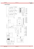
3. Block Diagram BMR GmbH 2014-03-17 E
Open the catalog to page 5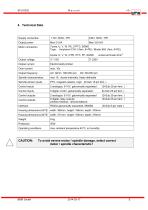
CAUTION: To avoid severe motor / spindle damage, select correct motor / spindle characteristic !
Open the catalog to page 6
5. Safety-Precautions and Warnings • This device produces dangerous electrical voltages and is used for the operation of dangerous moving mechanical parts. For this reason, only professionally trained and qualified personnel should be allowed to install and repair this device! • Before first activation of the device, verify, if it id in a faultless condition. If it was damaged during shipping and transportation it must not be switched on. • During installation the safety regulations have to be observed. • Before the device is turned on for the first time, it should be verified, that the connected...
Open the catalog to page 7
Operational parameters and outputs: The SFU-0302 covers all current important operational parameters and operating data. Up to 6 digital outputs can be used for signalling and up to 2 analogue values can be output to the analogue outputs (0-10V) . Remote Control and Outputs: 6 digital inputs (24 V) and 2 analogue inputs (0-10V) are available for remote control of the SFU-0302. These assignments can be freely configured. Using the optional Windows PC software SFU0302 the above assignments can be easily achieved, providing exceptional flexibility with each application Each operating parameter can...
Open the catalog to page 8
6.1 Digital and Analog I/Os (D-Sub 25pin fem.) Pin • The digital outputs (relays 1...6) are galvanically separated contacts (500VIsolation). D.C.: 24V / 1000mA A.C.: 125V / 500mA • Digital input switching level: "0" 0...7V "1" 18...24V • The digital inputs require a high level of 24 V for correct function (PLC standard level). • Hall sensor output level: 0-24V (24V level.) • Analogue input voltage range: 0...10V • The +24V output can be used as a power supply for this type of electronic spindle interface.
Open the catalog to page 9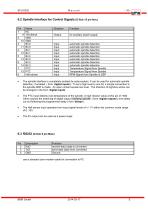
use a standard zero-modem-cable for connection to PC
Open the catalog to page 10
6.4 Spindle Connection on Round Connector (Female 6Pin+PE) 6 5 4 8 3 2 1 PTC PTC-Signal (Spindel temperature) W Spindle Phase 3 PTC PTC-Signal (Spindel temperature) PE Protective Earth GND Signal-GND for PTC-Signal U Spindle Phase 1 Amphenol C16-1 / Binder 693 with circular connector (Female 12Pin + PE) 5 Signal-GD for PTC + speed sensor 6 Signal speed sensor PE Protective Earth Spindle Other types of connectors or pinnings are possible on option 6.5 Mains Connection 3 pin Euro-Plug oder Screw Terminals
Open the catalog to page 11
Backpanel Spindle Interface
Open the catalog to page 12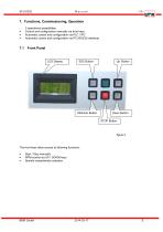
7. Functions, Commissioning, Operation 3 operational possibilities: • Control and configuration manually via front keys • Automatic control and configuration via PLC / IPC • Automatic control and configuration via PC (RS232 interface) The front keys allow access to following functions: • Start / Stop manually • RPM-control via UP / DOWN keys • Spindle characteristic selection
Open the catalog to page 13
7.2 LCD-Display All system data and parameter such as RPM, load or errors will be displayed on the LCD-display. The actual load output is displayed by bargraph and absolute in % in the bottom line of the display. The pre-selected duty RPM and spindle characteristic and the actual RPM of the spindle is displayed converter is running spindle characteristic 3 converter is in Stop State > spindle standstill converter is accelerating power output 67% converter is accelerating power output 34% spindle is rotating at duty RPM power output 20% Errors are displayed in the top line by text. Overload Stop...
Open the catalog to page 14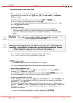
7.3 Configuration via the Front Keys STOP and OK , the Menu Spindle Characteristic Menu settings can only be adjusted when the device has come to a complete standstill. By simultaneously pressing the keys Setting will appear: Select the number of the spindle characteristic using the | UP | and DOWN keys. Spindle Characteristic : • Standard: A number of spindle characteristics are already implemented. Existing characteristics can be loaded and displayed using the PC software SFUTerminal. • Variants for Hofer motors: all spindle characteristics for Hofer-Motors are implemented exworks. The LCD...
Open the catalog to page 15
7.5 Starting and Stopping the Frequency Converter (all references to menues relate to setup software SFU-Terminal) There are different methods of starting and stopping SFU-0302 frequency converters, due to many different requirements, as follows below: • manually via panel keys • Remote control via digital input • Remote control via analogue input • Remote control via serial interface Before starting the converter is possible, a preset of the RPM (> 7.4) has to be done. This is necessary for all options of starting with the exception of analogue starting. Manually via panel keys _ Activation...
Open the catalog to page 16All BMR GmbH catalogs and technical brochures
 Catalogue
52 Pages
 SFU 0102
28 Pages
 SFU 400
15 Pages
 SFU 0102/0202
28 Pages
 SFU 0103/0203
30 Pages
 SFU 0303
56 Pages
 SFU0300
24 Pages
 SFU-ErrorFlags
7 Pages
 RS232 Control Commands
6 Pages
 SpindlecoolerKG-T 500
24 Pages
 DressView
32 Pages
 Folnet P S / P S 300
8 Pages
 Folnet P
8 Pages
 Folnet3-NT
8 Pages
 Folnet 1 NT
8 Pages
 Folnet 1
8 Pages
 Folinv 12/3
4 Pages
 SFU 0401
10 Pages
 SFU 0302 SSE
30 Pages
 SFU 0101/0201
17 Pages
 SFU 0100
2 Pages
 SFU 0303/4
48 Pages
 SFU 0303/2
50 Pages
 SFU0052
12 Pages
 SFU 0200/1
24 Pages
 SFU 0103
24 Pages
 SFU 0156
20 Pages
 SFU 0150
20 Pages
 KG-T 500
20 Pages

- Measuring machine
- Automatic measurement system
- Frequency inverter
- Measuring system for industrial applications
- Compact frequency inverter
- Digital output frequency inverter
- IP20 frequency inverter
- Motor frequency converter
- Vector control frequency inverter
- LED driver
- Integration frequency inverter
- Fieldbus frequency inverter
- Induction frequency converter
- Cabinet frequency inverter
- Low-voltage frequency inverter
- Asynchronous motor frequency inverter
- Vector-controlled frequency inverter
- Digital display frequency inverter
- Panel frequency inverter
- Synchronous motor frequency inverter