SFU 0156
1 /20Pages

SFU 0156
1 /20Pages
Catalog excerpts

Schnellfrequenzumrichter High Frequency Converters The Sign of Quality Made in Germany
Open the catalog to page 1
4.1 Power Supply Connection SL4 4 5 Description of Functions and Operation 5.2 Set Value of Rotational Speed 7
Open the catalog to page 3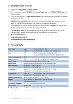
S Operation of AC spindles and BLDC spindles S The frequency converter SFU 0156 allows speed frequencies up to 2000Hz/120.000 rpm with 2-pole spindles. S The core of SFU-0156 is a digital signal processor (DSP) which produces all output parameters and collects signals. S High-precision sinusoidal output signals with a low distortion factor and low deformation allow for optimal rotation qualities in AC motors of all operating conditions S All parameters like power, voltage and frequency are collected in real time and are regulated by the implemented vector control depending on the load. S High...
Open the catalog to page 4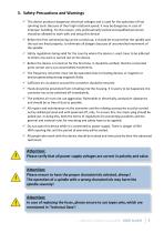
3. Safety-Precautions and Warnings This device produces dangerous electrical voltages and is used for the operation of fast spinning tools. Because of their high rotational speed, it may be dangerous in case of improper handling. For this reason, only professionally trained and qualified personnel should be allowed to work with and setup this device! Before the first commissioning can be carried out, it should be ensured that the spindle and the tool are fixed properly, to eliminate all dangers because of uncontrolled movement of the spindle. Safety regulations being valid for the country where...
Open the catalog to page 5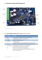
* X-ICD for internal use only 1 PE Protective Earth, is internally connected to mounting bracket 2 +80Vdc + Supply Voltage for spindle -> Fuse FS2 6,3 AT 3 0V (80V) Voltage return for spindle supply 4 PTC / KTY Temp sensor Spindle -> available at HW V1.1 and to be configured with SFU-Terminal >V6.25 5 0V (24V) Voltage return for controller supply (internally connected with PIN3) 6 +24V (max 30V) + Supply voltage for control logic -> Fuse FS1 250mAT protected against voltage reversal with Diode D8 NC Version SFU 0156 with onboard +24V logic supply. In this version...
Open the catalog to page 6
4 PE Protectiv Earth of spindle and cable shield 1 DI (Digital Input) Start / Stop 3 AI (Analog Input) Set value for rotational speed 2,4 Ground Ground Ref. for Pin 1, 3, 5, 7, 8, 9, 10 (internally connected withSL4.3/5) 6 AO (Analog Out) Output 0...10V (free configuration) Load Percent 7 DO2 Output (for free configuartion) (1) 8 +24V / 10mA max auxiliary supply (internally connected with SL4.6) Open Collector1 Converter Ready Open Collector3 Duty Speed reached The scaling of the analog input can be modified, as well as the function of the open collector outputs...
Open the catalog to page 7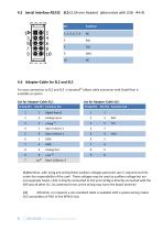
4.6 Adapter-Cable for SL2 and SL5 For easy connection to SL2 and SL5 a standard(2) ribbon cable connector with Dsub9 fem is available as option. List for Adapter-Cable SL5: D-Sub-Pin SL2-Pin Function SL2 (1)Attention, with using and wiring these auxiliary voltages particular care is required and lies under the responsibility of the user! These voltages may be used as auxiliary voltage but are not especially fused. +24V is directly connected to FS1 and +5Vdig is directly connected with the DSP and all other ICs. So, potential errors at the wiring may harm the board severely! (2) Attention, on...
Open the catalog to page 8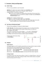
5.1 Start / Stop There are two possibilities to start the spindle: digitally with a digital control signal at digital inputl Start/Stop at SL2.1. The switching levels for "OFF=0" are 0...7V and for "ON=1" 18...24V, voltages between 7V and 18V are undefined. As soon as this is initiated, the spindle will be accelerated to the set value of the rotational speed which is pre-selected as voltage at analogue input1 Set Value of Rotational Speed at SL2.2. analogue with a voltage at analogue input1 Precondition is a valid "ON" signal at digital input1 Start/Stop An input voltage of 0V makes the spindle...
Open the catalog to page 9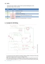
Likewise the open collector outputs, there are LEDs indicating the current operational status of the converter. Green Red Function Off Off Converter not ready A successful start of the spindle the analogue voltage at PIN3 as reference for the duty speed hast be higher than the minimum voltage (^ 5.2). With using a potentiometer for dialing the rotational speed it should be wired to 10V, so that the required range from 0...10V can be covered, representing the speed range. 8 I SFU 0156 Frequency Converter
Open the catalog to page 10
Safety Functions The following safety functions bring about controlled stop of the spindle according predefined deceleration times: Safety stop because of converter excess temperature after delay-time of 10s is exceeded Safety stop by overload and time delay exceeded (default 10sec) Safety stop will occur immediately by exceeding the maximum admissible spindle current. EMC (electromagnetic compatibility) The compliance with the limit values of EMC is the responsibility of the manufacturer of the machine or device. This device was developed for use in industrial environments. For trouble-free...
Open the catalog to page 11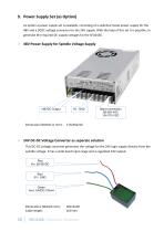
As option a power supply set is available, consisting of a switched mode power supply for the 48V and a DCDC voltage converter for the 24V supply. With the help of this set it is possible, to generate the required DC-supply voltages for the SFU0156. lhipMT 'W-ZWVAOSA > 24V DC-DC Voltage Converter as separate solution This DC-DC voltage converter generates the voltage for the 24V logic supply directly from the spindle voltage. It has a wide band input range and a regulated 24V output.
Open the catalog to page 12
Connection Diagramm of Power Supply Spindle Connector 48V Switched Mode Power Supply Cable Colours oft he 24V Voltage Converter Version with onboard +24V logic supply Spindel connector Spindle- and logic supply connector on board +24V logicsupply module Achtung: All these works handle with dangerous voltage and have to be carried out by skilled persons only. Please verify before connecting that the supply voltage is switched off! …when it comes to quality! BMR GmbH
Open the catalog to page 13
10. SFU 0156 with Remote Controller On option a remote controller is available which can directly be connected with the I/O interface at SL2. By this, the required duty speed can be adjusted with a potentiometer and the converter can be started and stopped with a rocker switch. The status of the digital outputs is indicated on LEDs. All required voltages are generated within this adapter, so the converter can be controlled and tested very easily. A quick test and setting into action of the converter becomes possible even without external control signals.
Open the catalog to page 14All BMR GmbH catalogs and technical brochures
 Catalogue
52 Pages
 SFU 0102
28 Pages
 SFU 400
15 Pages
 SFU 0102/0202
28 Pages
 SFU 0103/0203
30 Pages
 SFU 0303
56 Pages
 SFU0300
24 Pages
 SFU-ErrorFlags
7 Pages
 RS232 Control Commands
6 Pages
 SpindlecoolerKG-T 500
24 Pages
 DressView
32 Pages
 Folnet P S / P S 300
8 Pages
 Folnet P
8 Pages
 Folnet3-NT
8 Pages
 Folnet 1 NT
8 Pages
 Folnet 1
8 Pages
 Folinv 12/3
4 Pages
 SFU 0401
10 Pages
 SFU 0302 19”
28 Pages
 SFU 0302 SSE
30 Pages
 SFU 0101/0201
17 Pages
 SFU 0100
2 Pages
 SFU 0303/4
48 Pages
 SFU 0303/2
50 Pages
 SFU0052
12 Pages
 SFU 0200/1
24 Pages
 SFU 0103
24 Pages
 SFU 0150
20 Pages
 KG-T 500
20 Pages

- Measuring machine
- Automatic measurement system
- Frequency inverter
- Measuring system for industrial applications
- Compact frequency inverter
- Digital output frequency inverter
- IP20 frequency inverter
- Motor frequency converter
- Vector control frequency inverter
- LED driver
- Integration frequency inverter
- Fieldbus frequency inverter
- Induction frequency converter
- Cabinet frequency inverter
- Low-voltage frequency inverter
- Asynchronous motor frequency inverter
- Vector-controlled frequency inverter
- Digital display frequency inverter
- Panel frequency inverter
- Synchronous motor frequency inverter