SFU 0150
1 /20Pages

SFU 0150
1 /20Pages
Catalog excerpts
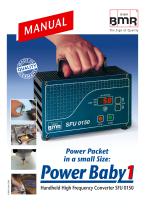
Power Packet in a small Size: Power Babvl Handheld High Frequency ConverterSFU 0150
Open the catalog to page 1
ongratulation for purchasing a BMR-GmbH product. We thank you for the decision for choosing a BMR-GmbH device and wish you much success. Please read this manual carefully before the first use Version 06.April.2009
Open the catalog to page 2
epending on its construction, the speed of a three-phase A.C. motor is directly dependent on the number of poles and the frequency of the network. In a 3ph 380V/50Hz network, with a 2-pole motor, the rated speed would be 50 U/s * 60 = 3000 Upm. With D.C. motors (brushless motor D.C.), the speed is dependent on the voltage applied. Three-phase A.C. motors provide numerous benefits in industry, such as brushless motor operation, long life, favourable performance/weight ratio, high-speed capability, and much more. These motors can be used in many different application areas, such as milling and...
Open the catalog to page 4
2 Description and Features For the operation of A.C. spindles. The high frequency converter SFU 0150 allows speed frequencies up to 50,000rpm with 2-pole A.C. spindles. Maximum High output power is (150VA) in a compact design. The core of the SFU 0150 is the Digital Signal Processor (DSP) which generates all output signals and captures all input signals. All parameters, such as current, voltage and frequency, are captured in real time, and are adjusted according to load condition by Vector Control Mode. The highest efficiency of motors at both low and high frequencies is made possible. Highest...
Open the catalog to page 5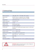
ATTENTION: Make sure that the setup for mains voltage is in accordance to the power line used.
Open the catalog to page 6
4 Safety Precautions and Warnings This device produces dangerous electrical voltages and is used for the operation of dangerous moving mechanical parts. For this reason, only professionally trained and qualified personnel should be allowed to install and work with this device! Any maintenance or repair work on the device must only be carried out when the mains supply plug has been disconnected! Before the first activation can be carried out, it should be established that the tool is installed correctly and securely, to eliminate the possibility of uncontrolled movement of the motor. Safety regulations...
Open the catalog to page 7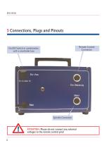
5 Connections, Plugs and Pinouts Remote Control Connector On/Off Switch in combination with a resettable fuse Spindle Connector ATTENTION: Please do not connect any external voltages to the remote control pins! 8
Open the catalog to page 8
5.1 Remote Control Connector (5 Pin) Pin Pin Pin Pin Pin Operation with footswitch BMR vario footcontroler Galvanically isolated contact = to FSW, B.M.R Footcontroler or contact = = = = to FSW, B.M.R Footcontroler or contact = ON/OFF. = ON-OFF- Variable rotational Speed. = Remote Control by a external PLC 3 pin butterfly mains connector. 5.4 Mains Switch and Fuse The mains switch is realized as a combination between a push-push button mains switch and a thermo protection fuse for 1A. Exeeding the rated current will trigger the thermo fuse to switch in the OFF Position Off Position
Open the catalog to page 9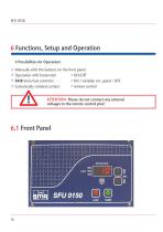
4 Possibilities for Operation: Manually with the buttons on the front panel Operation with footswitch = ON/OFF BMR Vario foot controler =ON/ variable rot. speed / OFF ■ Galvanically isolated contact = remote control ATTENTION: Please do not connect any external voltages to the remote control pins!
Open the catalog to page 10
6.2 Setup of Rotational Speed The rotational speed of a connected spindle or the frequency of the output voltage at the spindle terminals can be set up in several ways. Preselection manually via rpm buttons on the front panel The needed speed of rotation can be adjusted with the buttons on the front panel and is displayed on 3 digits on the LED-Display. During operation of the spindle the speed of rotation is displayed with 2 digits. Start, Stop and Setup with the B.M.R foot controler The maximum value of the rotational speed wished can set with the buttons on the front panel. From zero position...
Open the catalog to page 11
6.4 Setup of direction of rotation The direction of rotation may be changed before the start. To achieve this, the push buttons STOP and START have to be actuated simultaneously for about 5 sec (press Stop first, then Start) In this configuration mode it is possible to change the direction between clockwise (displayed: rE) and counterclockwise (displayed: Li) with the help of the RPM push buttons. If the push buttons are left unpressed for more than 10 sec, it is switched back to operating mode. 6.5 Operation If the converter is started and the spindle is spinning, the speed of rotation is displayed...
Open the catalog to page 12
7 Safety Functions A controlled spindle stop according to the preset acceleration data is carried out because of the events listed below. Converter switch-off, if maximum power consumption is exceeded constantly. In this case the thermofuse with the ON-OFF switch is triggered. Stop because of exceeding the max. internal temperature of the converter after a time delay of 10sec. Stop because of exceeding the max. nominal output load of the converter after a time delay of 10sec. Immediate-Stop because of exceeding maximum spindle current. 8 EMC Electro Magnetic Compatibility This device was developed...
Open the catalog to page 13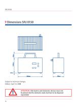
Subject to technical changes. Edition: April 12, 2008 ATTENTION: Old electric and electronic devices must not be placed into the domestic waste but have to be disposed separately! 14
Open the catalog to page 14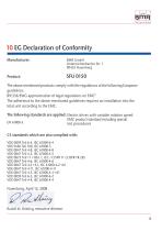
10 EG Declaration of Conformity Manufacturer: BMR GmbH Unterreichenbacher Str. 1 90455 Nuernberg The above mentioned products comply with the regulations of the following European guidelines: 89/336/EWG approximation of legal regulations on EMC" The adherence to the above mentioned guidelines requires an installation into the total unit according to the EMC. The following standards are applied: Electric drives with variable rotation speed EMC product standard including special EN 61800-3 test procedures C3 standards which are also complied with: VDE 0839 Teil 6-4, IEC 61000-6-4 VDE 0160 Teil...
Open the catalog to page 15
11 General Hints Our high frequency converters are highly valuable precison devices. Please take care of them with the necessary attention, to preserve their high precision, high power ability, and long lifetime. These devices leave our company only after a quality test and a load check have been carried out. Before mounting and use please read the attached manual carefully and pay attention to the points listed below. Before the first activation of the device, verify if it is in a faultless optical condition. If it was damaged during transportation, it must not be used and not turned on. During...
Open the catalog to page 16All BMR GmbH catalogs and technical brochures
 Catalogue
52 Pages
 SFU 0102
28 Pages
 SFU 400
15 Pages
 SFU 0102/0202
28 Pages
 SFU 0103/0203
30 Pages
 SFU 0303
56 Pages
 SFU0300
24 Pages
 SFU-ErrorFlags
7 Pages
 RS232 Control Commands
6 Pages
 SpindlecoolerKG-T 500
24 Pages
 DressView
32 Pages
 Folnet P S / P S 300
8 Pages
 Folnet P
8 Pages
 Folnet3-NT
8 Pages
 Folnet 1 NT
8 Pages
 Folnet 1
8 Pages
 Folinv 12/3
4 Pages
 SFU 0401
10 Pages
 SFU 0302 19”
28 Pages
 SFU 0302 SSE
30 Pages
 SFU 0101/0201
17 Pages
 SFU 0100
2 Pages
 SFU 0303/4
48 Pages
 SFU 0303/2
50 Pages
 SFU0052
12 Pages
 SFU 0200/1
24 Pages
 SFU 0103
24 Pages
 SFU 0156
20 Pages
 KG-T 500
20 Pages

- Measuring machine
- Automatic measurement system
- Frequency inverter
- Measuring system for industrial applications
- Compact frequency inverter
- Digital output frequency inverter
- IP20 frequency inverter
- Motor frequency converter
- Vector control frequency inverter
- LED driver
- Integration frequency inverter
- Fieldbus frequency inverter
- Induction frequency converter
- Cabinet frequency inverter
- Low-voltage frequency inverter
- Asynchronous motor frequency inverter
- Vector-controlled frequency inverter
- Digital display frequency inverter
- Panel frequency inverter
- Synchronous motor frequency inverter