SFU 0103
1 /24Pages

SFU 0103
1 /24Pages
Catalog excerpts
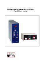
Frequency Converter SFU 0102/0202 Type SSE and desktop
Open the catalog to page 1
5 Safety Precautions and Warnings 6 Connections, Interfaces and Pinout 6.1 Digital and Analogue Inputs and Outputs 6.2 Spindle Power Output (Standard Round Connector) 6.3 Spindle Power Output (Clamps) 7 Functions, Commissioning, Operation 7.1 Configuration via the Front Keys 7.2 Configuration of rotational speed 7.3 Starting and Stopping the Frequency Converter 7.4 Remote Controlled Configuration of Direction of Rotation 7.5 Safety Stop Functions 7.6 Control via LED Front Board 7.7 Spindle Diagram Set Up on LED Front Panel 8 Calibration and Configuration using...
Open the catalog to page 2
1. Introduction Depending on its construction, the speed of a three-phase a.c. motor is directly dependent on the number of poles and the frequency of the network. In a 3ph 380V/50Hz network, with a 2-pole motor, the rated speed would be 50 U/s * 60 = 3000 Upm. With d.c. motors (brushless d.c.), the speed is dependent on the voltage applied. Three-phase a.c. motors provide numerous benefits in industry, such as brushless operation, freedom from wear and tear, favourable capacity/weight ratio, high-speed capability, and much more. These motors can be used many different application areas, such...
Open the catalog to page 3
• Operation of a.c. and bldc spindles • The frequency converter SFU 0102/0202 allows speed frequencies up to 120,000Upm with 2-pole a.c. motors and 60,000Upm with bldc-motors. • Output power ( 250VA-0102 / 400VA-0202 ) • The Kernel of the SFU-0302 is a Digital Signal Processor (DSP), which generates all output variables and captures signals. • All parameters, such as current, voltage and frequency, are captured in real time, and adjusted by implementing via the Vector Control according to loading. • The highest efficiency of motors at both low and high frequencies is made possible. • High level...
Open the catalog to page 4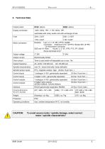
CAUTION: To avoid severe motor / spindle damage, select correct motor / spindle characteristic !
Open the catalog to page 6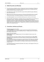
This device produces dangerous electrical voltages and is used for the operation of dangerous moving mechanical parts. For this reason, only professionally trained and qualified personnel should be allowed to install and repair this device! Any maintenance or repair work to the device may be carried out after the supply voltage has been disconnected only! Before the first set to action can be carried out, it should be ensured that the motor is installed correctly and securely, to eliminate the possibility of uncontrolled movement of the motor. Local safety regulations have to be observed while...
Open the catalog to page 7
Pin 1 = common connection for relays Pin 2 = Relay 1 (normally open) Pin 3 = Relay 2 (normally closed) Pin 9 = Relay 3 (normally open) Pin 10 = Relay 4 (normally closed) Pin 6 = Relay 5 (normally open) Pin 4 = Analogue Output (depending on Model) Pin 11 = Analogue Input Pin 8 = Ground Pin 12 = Digital Input 1 Pin 15 = Digital Input 2 Pin 5 = Digital Input 3 Pin 13 = RxD Pin 14 = TxD Pin 7 = Impulse magneto resistor factory default function Rotational Speed Reached (desired- / actual - value) Superheat (converter or spindle) Standstill of Spindle (desired- / actual - value) Overload Spindle Converter...
Open the catalog to page 8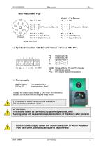
NC R S 3 Phases for Spindle T + PTC + Hall Sensor Signal Ground Model +5 V Sensor Pin 1 = NC Pin 2 = R Pin 3 = S 3 Phases for Spindle Pin 4 = T Pin 5 = +5 V Pin 6 = + Hall Sensor Pin 7 = Signal Ground view from front SGND Signal-GND for FP- and PTC-Signals FP Hall-Sensor-Signal PTC PTC-Signal (Spindle temperature) 6.4 Mains supply desktop device: 3 pin. standard plug To adapt the mains supply voltage to 230V and 115V networks a selection can be done with the help of a rotary switch Alt is important to select the appropriate mains fuse ! The required value is listed under 4. A ATTENTION: This...
Open the catalog to page 9
7. Functions, Commissioning, Operation • • • 3 operational possibilities: Control and configuration manually via front keys Automatic control and configuration via PLC / IPC Automatic control and configuration via PC (RS232 interface) Setup and control of the features and functions listed below can be carried out with our setup software SFU-Terminal. All explanations and hints to menu functions relate to this software. The operation of a spindle with a wrong spindle characteristic may cause severe damages at spindle or converter. To avoid this, please ensure that the correct spindle characteristic...
Open the catalog to page 10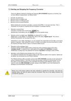
7.2 Starting and Stopping the Frequency Converter There are different methods of starting and stopping SFU 0102/0202 frequency converters, due to many different requirements, as follows below: • • • • manually via panel keys Remote control via digital input Remote control via analogue input Remote control via serial interface Before starting the converter is possible, a preset of the RPM (> 7.4) has to be done. This is necessary for all options of starting with the exception of analogue starting. Manually via panel keys Activation of spindle start via the green START key. Spindle-stop is activated...
Open the catalog to page 11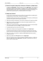
7.3 Remote-Controlled Configuration of Direction of Rotation via Digital Inputs Via digital input RPM direction . Setup is carried out in menu ‘digital inputs’. This is necessary, if the direction of rotation has to be controlled , for example, via a PLC. Reversal can only take place once the spindle / motor has come to a complete stop. If the direction pre-selection setting is changed whilst the spindle / motor is running, the spindle / motor will not turn in the new direction until it has been brought to a complete standstill and then restarted. 7.4 Safety stop functions As shown above, all...
Open the catalog to page 12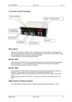
7.5 Control via LED Front Board LED Load Display Display of Rotational Speed LED Display for Converter Status Mains Switch RPM Poti STOP Button START Button Mains Switch After the Power-button is switched "ON", the Frequency Converter starts an automatically selftest for about 8 seconds. During this time all displays flashes a short time one after another. After this automatical check the converter is ready for operation. In case of defect the corresponding display flashes. Spindle "Start" After pressing the „START“-button the spindle starts to come up to the rotational speed adjusted by the...
Open the catalog to page 13All BMR GmbH catalogs and technical brochures
 Catalogue
52 Pages
 SFU 0102
28 Pages
 SFU 400
15 Pages
 SFU 0102/0202
28 Pages
 SFU 0103/0203
30 Pages
 SFU 0303
56 Pages
 SFU0300
24 Pages
 SFU-ErrorFlags
7 Pages
 RS232 Control Commands
6 Pages
 SpindlecoolerKG-T 500
24 Pages
 DressView
32 Pages
 Folnet P S / P S 300
8 Pages
 Folnet P
8 Pages
 Folnet3-NT
8 Pages
 Folnet 1 NT
8 Pages
 Folnet 1
8 Pages
 Folinv 12/3
4 Pages
 SFU 0401
10 Pages
 SFU 0302 19”
28 Pages
 SFU 0302 SSE
30 Pages
 SFU 0101/0201
17 Pages
 SFU 0100
2 Pages
 SFU 0303/4
48 Pages
 SFU 0303/2
50 Pages
 SFU0052
12 Pages
 SFU 0200/1
24 Pages
 SFU 0156
20 Pages
 SFU 0150
20 Pages
 KG-T 500
20 Pages

- Measuring machine
- Automatic measurement system
- Frequency inverter
- Measuring system for industrial applications
- Compact frequency inverter
- Digital output frequency inverter
- IP20 frequency inverter
- Motor frequency converter
- Vector control frequency inverter
- LED driver
- Integration frequency inverter
- Fieldbus frequency inverter
- Induction frequency converter
- Cabinet frequency inverter
- Low-voltage frequency inverter
- Asynchronous motor frequency inverter
- Vector-controlled frequency inverter
- Digital display frequency inverter
- Panel frequency inverter
- Synchronous motor frequency inverter