SFU 0103/0203
1 /30Pages

SFU 0103/0203
1 /30Pages
Catalog excerpts
Digital and Analogue Inputs and Outputs 7 Digital and Analogue Inputs and Outputs 8 Spindle Power Output (Standard Round Connector 8 Spindle Power Output (Clamps) 9 Mains Supply 9 Configuration via the Front Keys Starting and Stopping the Frequency Converter Remote Control Possibilities Remote Controlled Configuration of Direction of Rotation Control via LED Front Panel LED Displays Error message – Error numbers Setting up the Spindle Number at the Front Panel Safety Functions
Open the catalog to page 3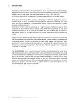
Depending on its construction, the speed of a three‐phase asynchronous AC motor is directly dependent on the number of poles and the frequency of the voltage network. In a 3ph/50Hz network, with a 2‐pole motor, the rated speed would be 50 U/s * 60 = 3000 rpm. With synchronous motors (brushless DC), the speed is dependent on the voltage applied Three‐phase AC motors offer numerous advantages in industrial applications, such as brushless drive, no wear, favourable power/weight ratio, high speed capability, and much more. Your field of application is correspondingly diverse, e.g. for driving spindles in milling, ...
Open the catalog to page 4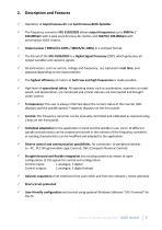
Operation of Asynchronous‐AC and Synchronous‐BLDC‐Spindles The frequency converter SFU 0103/0203 allows output frequencies up to 4000 Hz / 240.000rpm with 2‐pole asynchronous‐AC‐motors and 1667Hz/ 100.000rpm with synchronous‐BLDC‐motors. Output power ( 300VA/S1‐100% / 480VA/S1‐100%) in a compact format The Kernel of the SFU‐0103/0203 is a Digital Signal Processor (DSP), which generates all output variables and captures signals. All parameters, such as current, voltage and frequency, are captured in real time, and adjusted depending on the load condition The highest efficiency of motors at both low and high frequencies is made possible. ...
Open the catalog to page 5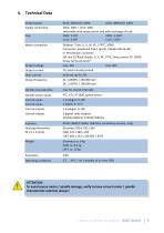
4. Technical Data Output power Supply connection Fuse Control inputs Control inputs
Open the catalog to page 7
5. Safety‐Precautions and Warnings This device produces dangerous electrical voltages and is used for the operation of fast spinning tools. Because of their high rotational speed, it may be dangerous in case of improper handling. For this reason, only professionally trained and qualified personnel should be allowed to work with and setup this device! Before the first commissioning can be carried out, it should be ensured that the spindle and the tool are fixed properly, to eliminate all dangers because of uncontrolled movement of the spindle. All repairs and maintenance on the converter and the relating accessories must be carried out ...
Open the catalog to page 8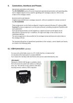
6. Connections, Interfaces and Pinouts Operational parameters and outputs: The SFU 0103/0203 covers all current important operational parameters and operating data. Up to 5 digital outputs can be used for signalling and 1 analogue value (0...10V) can be output at the analogue output. Remote Control and Outputs: 3 digital inputs (0/24V) and 1 analogue inputs (0...10V) are available for remote control of the SFU 0103/0203. These assignments can be freely configured. Using the optional Windows PC software SFU‐ Terminal the above assignments can be easily achieved, providing exceptional flexibility with ...
Open the catalog to page 9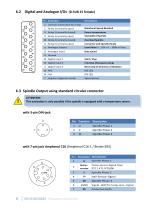
with 7-pin jack Amphenol C16 (Amphenol C16-1 / Binder 693) Pin
Open the catalog to page 10
+ Hall / Speed Sensor Signal Ground Speed / Temp Signal Signal‐GND for FP‐and Temperaturesensor‐Signals Hall‐Sensor‐Signal Temperature‐ Temp.sens.‐Signal sensor (Spindle temperatur) 5V ATTENTION: This setting has to be carried out by qualified personal, only! A wrong setup will cause immediate destructions of the device after power on
Open the catalog to page 11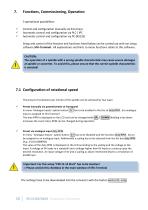
7. Functions, Commissioning, Operation 3 operational possibilities: Control and configuration manually via front keys Automatic control and configuration via PLC / IPC Automatic control and configuration via PC (RS232) Setup and control of the features and functions listed below can be carried out with our setup software SFU‐Terminal. All explanations and hints to menu functions relate to this software. CAUTION: The operation of a spindle with a wrong spindle characteristic may cause severe damages at spindle or converter. To avoid this, please ensure that the correct spindle characteristic ...
Open the catalog to page 12
7.2 Starting and Stopping the Frequency Converter There are different methods of starting and stopping SFU 0103/0203 AC/DC frequency converters, due to many different requirements, as follows below: manually via panel keys Remote control via digital input Remote control via analogue input Remote control via serial interface Manually via panel keys Activation of spindle start via the green START key. Spindle‐stop is activated by the red STOP key on the operator panel. Remote control via digital input Start/Stop by external PLC or CNC Digital Input 1 is the default. To change this, click on the menu ‘digital inputs’. The correct ...
Open the catalog to page 13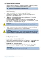
ATTENTION: If an operating mode for starting the inverter has been selected from the list above, it an also only be stopped in this operating mode. This does not apply to the safety functions
Open the catalog to page 14
The emergency shutdown interlock can be programmed by software „active“ or „inactive“. Programming „inactive“ is insignificant, whereas with a „active“ programming a primary stop‐ command can be given. This means that the converter cannot be started again neither by the „Start‐button“ nor by the remote‐control and that the spindle will be controlled slowed down. To abolish the command „shutdown‐interlock“ there has to be applied a voltage of 5V...30V on the control connector Pin 15 (+) and Pin 8 (⊥). In menu "digital inputs" (SFU‐Terminal) the function RPM direction .can be linked with one ...
Open the catalog to page 15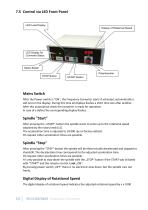
LED Load Display Display of Rotational Speed LED Display for Converter Status Mains Switch Potentiometer STOP Button START Button After the Power‐switch is "ON", the Frequency Converter starts if activated, automatically a self‐test on the display. During this time all displays flashes a short time one after another. After this automatical check the converter is ready for operation. In case of a defect the corresponding display flashes. After pressing the "STOP"‐button the spindle will be electronically decelerated and stopped to standstill. The deceleration time corresponds to the adjusted acceleration time. ...
Open the catalog to page 16All BMR GmbH catalogs and technical brochures
 Catalogue
52 Pages
 SFU 0102
28 Pages
 SFU 400
15 Pages
 SFU 0102/0202
28 Pages
 SFU 0303
56 Pages
 SFU0300
24 Pages
 SFU-ErrorFlags
7 Pages
 RS232 Control Commands
6 Pages
 SpindlecoolerKG-T 500
24 Pages
 DressView
32 Pages
 Folnet P S / P S 300
8 Pages
 Folnet P
8 Pages
 Folnet3-NT
8 Pages
 Folnet 1 NT
8 Pages
 Folnet 1
8 Pages
 Folinv 12/3
4 Pages
 SFU 0401
10 Pages
 SFU 0302 19”
28 Pages
 SFU 0302 SSE
30 Pages
 SFU 0101/0201
17 Pages
 SFU 0100
2 Pages
 SFU 0303/4
48 Pages
 SFU 0303/2
50 Pages
 SFU0052
12 Pages
 SFU 0200/1
24 Pages
 SFU 0103
24 Pages
 SFU 0156
20 Pages
 SFU 0150
20 Pages
 KG-T 500
20 Pages

- Measuring machine
- Automatic measurement system
- Frequency inverter
- Measuring system for industrial applications
- Compact frequency inverter
- Digital output frequency inverter
- Motor frequency converter
- IP20 frequency inverter
- Vector control frequency inverter
- LED driver
- Integration frequency inverter
- Fieldbus frequency inverter
- Induction frequency converter
- Cabinet frequency inverter
- Low-voltage frequency inverter
- Asynchronous motor frequency inverter
- Vector-controlled frequency inverter
- Digital display frequency inverter
- Synchronous motor frequency inverter
- PROFIBUS frequency inverter