SFU 0102
1 /28Pages

SFU 0102
1 /28Pages
Catalog excerpts

…when it comes to quality! BMR GmbH
Open the catalog to page 1
Issue June 2016 1 Introduction 5 Safety Precautions and Warnings 6 Connections, Interfaces and Pinout Digital and Analogue Inputs and Outputs Spindle Power Output (Standard Round Connector Spindle Power Output (Clamps) Mains Supply Configuration via the Front Keys Configuration of rotational speed Starting und Stopping the Frequency Converter Remote Controlled Configuration of Direction of Rotation Safety Stop Functions Control via LED Front Board Spindle Diagram Set Up on LED Front Panel 8 Calibration and Configuration using Windows Software 10 EMC (Electronic- Magnetic Compatibility) …when...
Open the catalog to page 3
Introduction Depending on its construction, the speed of a three-phase a.c. motor is directly dependent on the number of poles and the frequency of the network. In a 3ph 380V/50Hz network, with a 2-pole motor, the rated speed would be 50 U/s * 60 = 3000 Upm. With d.c. motors (brushless d.c.), the speed is dependent on the voltage applied Three-phase a.c. motors provide numerous benefits in industry, such as brushless operation, freedom from wear and tear, favourable capacity/weight ratio, high-speed capability, and much more. These motors can be used many different application areas, such as...
Open the catalog to page 4
Description and Features Operation of a.c. and bldc spindles The frequency converter SFU 0102/0202 allows output frequencies up to 200 Hz / 120,000Upm with 2-pole AC motors and 1000Hz/ 60,000Upm with Bloc-motors. Output power ( 250VA-0102 / 400VA-0202 ) The Kernel of the SFU-0302 is a Digital Signal Processor (DSP), which generates all output variables and captures signals. All parameters, such as current, voltage and frequency, are captured in real time, and adjusted by implementing via the Vector Control according to loading. The highest efficiency of motors at both low and high frequencies...
Open the catalog to page 5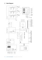
Block Diagram
Open the catalog to page 6
Technical Data Output power Supply connection Fuse Motor connection Output voltage Desktop: 7-pin: U, V, W, PE, 2*PTC, SGND Connector: Amphenol C16-1 (6+PE) / Binder 693 (6+PE) or Hirschmann connector SSE and 19"Rack: 8-pole: U, V, W, 2*PE, PTC, FP, SGND Screw terminals 4mm² max. 36V max. 60V Output current Electronically limited Output frequency Spindle characteristics max 16, stored internally, freely definable Spindle sensor inputs Control inputs Control inputs 1 analogue: 0-10V, galvanically separeted 3 digital: 0- 24, galvanically separeted Control outputs 1 analogue: 0-10V, galvanically...
Open the catalog to page 7
Safety-Precautions and Warnings This device produces dangerous electrical voltages and is used for the operation of fast spinning tools. Because of their high rotational speed, it may be dangerous in case of improper handling. For this reason, only professionally trained and qualified personnel should be allowed to work with and setup this device! Before the first commissioning can be carried out, it should be ensured that the spindle and the tool are fixed properly, to eliminate all dangers because of uncontrolled movement of the spindle. Safety regulations being valid for the country where...
Open the catalog to page 8
Connections, Interfaces and Pinouts Operational parameters and outputs: The SFU 0102/0202 covers all current important operational parameters and operating data. Up to 6 digital outputs can be used for signalling and up to 1 analogue values can be output to the analogue outputs (0-10V). Remote Control and Outputs: 6 digital inputs (24V) and 1 analogue inputs (0-10V) are available for remote control of the SFU 0102/0202. These assignments can be freely configured. Using the optional Windows PC software SFUTerminal the above assignments can be easily achieved, providing exceptional flexibility...
Open the catalog to page 9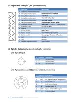
6.1 Digital and Analogue I/Os (D-SUB 15 female) Description common connection for relays Relay 1 (normally open) Relay 2 (normally closed) Relay 3 (normally open) Rotational Speed Reached (desired- / actual - value) Superheat (converter or spindle) Standstill of Spindle (desired- / actual - value) Overload Spindle 10 Relay 4 (normally closed) Relay 5 (normally open) 4 Analogue Output 11 (depending on Model) Analogue Input Converter and Spindle Ready Load Value 0 … 10V = 0 … 100% or Duty Rotational Speed of Spindle Drehzahlvorgabe Start / Stop Interlock (Emergency Stop) Reversing of Direction...
Open the catalog to page 10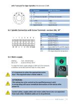
with 7-pin jack for Jäger-Spindles (Hirschmann C164) Model +5 V Sensor + Hall Sensor Signal Ground + Hall Sensor Signal Ground 6.3 Spindle Connection with Screw Terminals versions SSE, 19“ Function Protective Earth Spindle Phase 2 Spindle Phase 3 Signal-GND for FP-and PTC-Signals Hall-Sensor-Signal PTC-Signal (Spindle temperatur) Protective Earth Spindle Phase 1 6.4 Mains supply desktop: SSE or 19": 3 pin. standard plug Screw terminals, 4mm2 To adapt the mains supply voltage to 230V and 115V networks a selection can be done with the help of a rotary switch It is important to select the appropriate...
Open the catalog to page 11
Functions, Commissioning, Operation 3 operational possibilities: Control and configuration manually via front keys Automatic control and configuration via PLC / IPC Automatic control and configuration via PC (RS232 interface) Setup and control of the features and functions listed below can be carried out with our setup software SFU-Terminal. All explanations and hints to menu functions relate to this software. CAUTION: The operation of a spindle with a wrong spindle characteristic may cause severe damages at spindle or converter. To avoid this, please ensure that the correct spindle characteristic...
Open the catalog to page 12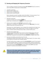
7.2 Starting and Stopping the Frequency Converter There are different methods of starting and stopping SFU 0102/0202 frequency converters, due to many different requirements, as follows below: manually via panel keys Remote control via digital input Remote control via analogue input Remote control via serial interface Before starting the converter is possible, a preset of the RPM (> 7.4) has to be done. This is necessary for all options of starting with the exception of analogue starting. Manually via panel keys Activation of spindle start via the green START key. Spindle-stop is activated by...
Open the catalog to page 13All BMR GmbH catalogs and technical brochures
 Catalogue
52 Pages
 SFU 400
15 Pages
 SFU 0102/0202
28 Pages
 SFU 0103/0203
30 Pages
 SFU 0303
56 Pages
 SFU0300
24 Pages
 SFU-ErrorFlags
7 Pages
 RS232 Control Commands
6 Pages
 SpindlecoolerKG-T 500
24 Pages
 DressView
32 Pages
 Folnet P S / P S 300
8 Pages
 Folnet P
8 Pages
 Folnet3-NT
8 Pages
 Folnet 1 NT
8 Pages
 Folnet 1
8 Pages
 Folinv 12/3
4 Pages
 SFU 0401
10 Pages
 SFU 0302 19”
28 Pages
 SFU 0302 SSE
30 Pages
 SFU 0101/0201
17 Pages
 SFU 0100
2 Pages
 SFU 0303/4
48 Pages
 SFU 0303/2
50 Pages
 SFU0052
12 Pages
 SFU 0200/1
24 Pages
 SFU 0103
24 Pages
 SFU 0156
20 Pages
 SFU 0150
20 Pages
 KG-T 500
20 Pages

- Measuring machine
- Automatic measurement system
- Frequency inverter
- Measuring system for industrial applications
- Compact frequency inverter
- Digital output frequency inverter
- Motor frequency converter
- IP20 frequency inverter
- Vector control frequency inverter
- LED driver
- Integration frequency inverter
- Fieldbus frequency inverter
- Induction frequency converter
- Cabinet frequency inverter
- Low-voltage frequency inverter
- Asynchronous motor frequency inverter
- Vector-controlled frequency inverter
- Digital display frequency inverter
- Synchronous motor frequency inverter
- PROFIBUS frequency inverter