SFU 0101/0201
1 /17Pages

SFU 0101/0201
1 /17Pages
Catalog excerpts

STATIC FREQUENCY CONVERTER
Open the catalog to page 1
♦ Elements for operation and Technical Data4 ♦ Connection5 SFU 0101 - 0201 SSE6 ♦ Elements for operation and Technical Data6 ♦ Connection7 SFU 1901 -1902 19’’-Rack8 ♦ Elements for operation and Technical Data8 ♦ Connection9 • GENERAL12 • POWER SWITCH12 • SPINDLE „START“12 • SPINDLE „STOP“12 • DIGITAL DISPLAY FOR RATIATIONAL SPEED12 • DISPLAY FOR CONVERTER13 • DISPLAY FOR SPINDLE13 • LOAD DISPLAY13 • OVERLOAD DISPLAY13 • OVERLOAD POWER CUT14 • EXCESS TEMPERATURE OF CONVERTER14 • EXCESS TEMPERATURE OF SPINDLE14 • REMOTE CONTROL15 • ROTATIONAL SPEED REACHED15 • STANDTILL OF SPINDLE16 • CONFIG. 1:...
Open the catalog to page 2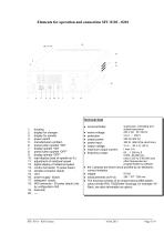
Technical Data ♦ microcontroller: ♦ mains voltage: ♦ protection: ♦ output power: ♦ power input: ♦ output voltage: ♦ maximum output current: ♦ frequency range: 1. housing 2. display for changer 3. display for spindle 4. power switch 5. manufacturers emblem 6. press button spindle "ON" 7. display spindle "ON" 8. press button spindle "OFF" 9. display spindle "OFF" 10. load display (load of spindle as %) 11. adjustment of rotational speed 12. digital display of rotational speed 13. control connector 15 poles (back) 14. spindle connector (back) 15. vent 16. power supply (back) 17. safeguard (back) 18....
Open the catalog to page 3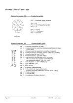
Pin 1 = rotational speed knowing Pin 2 = R Pin 3 = S 3 Phases for spindle Pin 4 = T Pin 5 = + PTC Pin 6 = + field panel Pin 7 = Ground front view pin 1 = common connection for relay pin 2 = make contact by reaching rotational speed (desired value / active value) pin 3 = break contact by superheat (converter or spindle) pin 9 = make contact by standstill ( desired value / active value) pin 10 = break contact by load >100% pin 6 = make contact by ..converter ready" pin 4 = dependent on configuration of the converter: dC Out-active value spindle 1V / 10000 Upm DC Out-active...
Open the catalog to page 4
O SDindel-UbertemDeratuO _ O SDindel nicht bereit START — O Drehzahl erreicht (^) NETZ HF Spindel 1. housing 2. display for changer 3. display for spindle 4. — 5. manufacturers emblem 6. press button spindle "ON" 7. display spindle "ON" 8. press button spindle "OFF" 9. display spindle "OFF" 10. load display (load of spindle as %) 11. adjustment of rotational speed 12. digital display of rotational speed 13. control connector - 15 poles (back) 14. spindle connector - 7 poles (back) 15. vent 16. power supply (back) 17. RS 232 1 8. ---- Technical Data ♦ microcontroller: ♦ mains voltage: ♦...
Open the catalog to page 5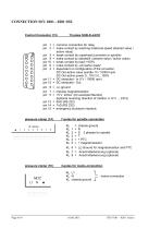
pin 1 = common connection for relay pin 2 = make contact by reaching rotational speed (desired value / active value) pin 3 = break contact by superheat (converter or spindle) pin 9 = make contact by standstill ( desired value / active value) pin 10 = break contact by load >100% pin 6 = make contact by ..converter ready" pin 4 = dependent on configuration of the converter: DC Out-active value spindle 1V / 10000 Upm DC Out-active power 0...10V £ 0...100% pin 11 = DC sheduled - In (1V / 10000 rpm) pin 12 = DC sheduled - Out pin 5 = +5 V 40mA (for example fiberotic)...
Open the catalog to page 6
1. housing 2. display for changer 3. display for spindle 4. power switch 5. manufacturers emblem 6. press button spindle "ON" 7. display spindle "ON" 8. press button spindle "OFF" 9. display spindle "OFF" 10. load display (load of spindle as %) 11. adjustment of rotational speed 12. digital display of rotational speed 13. control connector - 15 poles (back) 14. spindle connector - 7 poles (back) 15. vent 16. power supply (back) 17. safeguard (back) 18. — 19. — 20. ---- ♦ microcontroller: ♦ mains voltage: ♦ protection: ♦ output power: ♦ power input: ♦ output voltage: ♦ maximum output current: ♦...
Open the catalog to page 7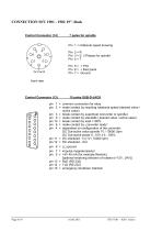
Pin 1 = rotational speed knowing Pin 2 = R Pin 3 = S 3 Phases for spindle Pin 4 = T Pin 5 = + PTC Pin 6 = + field panel Pin 7 = Ground front view pin 1 = common connection for relay pin 2 = make contact by reaching rotational speed (desired value / active value) pin 3 = break contact by superheat (converter or spindle) pin 9 = make contact by standstill ( desired value / active value) pin 10 = break contact by load >100% pin 6 = make contact by ..converter ready" pin 4 = dependent on configuration of the converter: dC Out-active value spindle 1V / 10000 Upm DC Out-active...
Open the catalog to page 8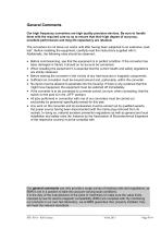
General Comments Our high frequency converters are high quality precision devices. Be sure to handle them with the required care so as to ensure that their high degree of accuracy, excellent performance and long life expectancy are retained. The converters do not leave our works until after having been subjected to an extensive „load test“. Before installing the equipment, carefully read the instructions supplied with it. Additionally, the following rules should be observed: • Before commissioning, see that the equipment is in perfect condition. If the converter has • • • • • • • been damaged...
Open the catalog to page 9
Operating Instructions GENERAL This Static Frequency Converter includes a microcontroller, which controls, supervises and regulates all functions, such as analogue and digital interfaces, evaluations, data inputs, respectively effective transmission-parameters; which can also be changed by software. POWER SWITCH After the Power-button is switched "ON"; the Static Frequency Converter starts an automatically check for about 8 seconds. During this time all displays flashes a short time one after another. After this automatical check the converter is ready for operation. In case of defect the corresponding...
Open the catalog to page 10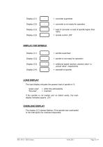
= converter is not ready for operation = load of converter or load of spindle higher than 100% = spindle is not ready for operation = rotational speed reaches „desired value“ or „actual value“, respectively LOAD DISPLAY The load display indicates the present load of spindle in %. "green area" "red area" = within the admissibility = overload If the spindle is not loaded and no defect exists, the loaddisplay indicates approx. „0%“. OVERLOAD DISPLAY The display (2.3) always flashes, if the spindle was overloaded or the interruption for overload responded.
Open the catalog to page 11All BMR GmbH catalogs and technical brochures
 Catalogue
52 Pages
 SFU 0102
28 Pages
 SFU 400
15 Pages
 SFU 0102/0202
28 Pages
 SFU 0103/0203
30 Pages
 SFU 0303
56 Pages
 SFU0300
24 Pages
 SFU-ErrorFlags
7 Pages
 RS232 Control Commands
6 Pages
 SpindlecoolerKG-T 500
24 Pages
 DressView
32 Pages
 Folnet P S / P S 300
8 Pages
 Folnet P
8 Pages
 Folnet3-NT
8 Pages
 Folnet 1 NT
8 Pages
 Folnet 1
8 Pages
 Folinv 12/3
4 Pages
 SFU 0401
10 Pages
 SFU 0302 19”
28 Pages
 SFU 0302 SSE
30 Pages
 SFU 0100
2 Pages
 SFU 0303/4
48 Pages
 SFU 0303/2
50 Pages
 SFU0052
12 Pages
 SFU 0200/1
24 Pages
 SFU 0103
24 Pages
 SFU 0156
20 Pages
 SFU 0150
20 Pages
 KG-T 500
20 Pages

- Measuring machine
- Automatic measurement system
- Frequency inverter
- Measuring system for industrial applications
- Compact frequency inverter
- Digital output frequency inverter
- IP20 frequency inverter
- Motor frequency converter
- Vector control frequency inverter
- LED driver
- Integration frequency inverter
- Fieldbus frequency inverter
- Induction frequency converter
- Cabinet frequency inverter
- Low-voltage frequency inverter
- Asynchronous motor frequency inverter
- Vector-controlled frequency inverter
- Digital display frequency inverter
- Panel frequency inverter
- Synchronous motor frequency inverter