KG-T 500
1 /20Pages

KG-T 500
1 /20Pages
Catalog excerpts

The Sign of Quality Made in Germany Kuhlgerat Cooling unit
Open the catalog to page 1
12 Other products of BMR GmbH 15
Open the catalog to page 3
General description The cooling unit KG-T 500 is controlled by an internal microprocessor. It has been designed to run high speed spindles like in cool ambience conditions. You are able to use it nearly for all types of spindles and cooling blocks. The maximum range of spindle power is 2000W. The KG-T 500 has an integrated and intelligent cooling fluid control. It depends on the temperature of the cooling fluid. According to requirements the fan power will be set to get more or less cooling power. This system runs always in an automatic mode and the users do not need any setting before starting...
Open the catalog to page 4
2. Safety instructions In case of current overload or short circuit you have to be ensured, that the KG-T 500 will be disconnected to power supply. The cooling unit should never operate in an unsupervised run. Be careful by filling the tank of the KG-T 500. Wrong bearing fluid should be immediately taken off by a sponge or a try cloths. Before filling the KG-T 500 with cool fluid, please check the power supply. It should be separated from the cooler und control the de-energized mode of the system. Before starting the KG-T 500 please check all screw connection, cables, pipes and gaskets. Use only...
Open the catalog to page 5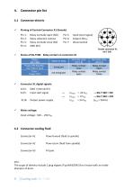
Connector pin list 4.1 Connector electric Pinning of Control-Connector X1 (female) Pin 1: Relay normally open (NO) Pin 2: Relay collective contact Pin 3: Relay normally close (NC) Status of KG-T500: Relay contact on connector X1 ✓ Connector X1 digital signals: X1/4: GND (internal 0V) X1/5: Input start signal X1/6: Output power supply ✓ Mains voltage: Input voltage: 100 ... 250 VAC 4.2 Connector cooling fluid Connector A1 Connector A2 Connector A3 Flow forward (fluid to spindle) Flow return (fluid from spindle) Fill port Info: The scope of delivery include 2 plug nipples (Typ...
Open the catalog to page 6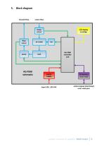
Block diagram …when it comes to quality! BMR GmbH
Open the catalog to page 7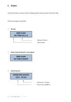
On the front panel you have a 16x2 LCD display which shows all modes of the KG-T 500. All these messages are possible: BMR GmbH KG-T500 Vers:1.3 Software Version Typ of cooler Ready mode (waiting for a start signal): Operating time: OPERATING-HOURS: 124 h 23 min Minutes (0 – 59 min) Hours (max. 60.000 h)
Open the catalog to page 8
Tr: 23C *1,2 L/minTa: 21C FAN: 80% ik a Fanpower (30 - 100%) Temperatures: Return Tr and Air Ta ERROR! FAN STOP Check FAN S Error message: FLOW Flow is less than 0,5l/min Fluid temperature to high S Error message: Over temperature ERROR! TEMP>50C !!! STOP !!! S Nachlaufsteuerung: STOP in 5 Min. Follow-up timer No start signal, autocontrol activ
Open the catalog to page 9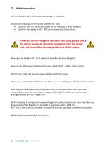
Initial operation At first, check the KG-T 500 for external damages of transport. Connect the fluid pipes of the spindle with the KG-T 500 : • Fluid from the KG-T 500 to the spindle set on connector 1 (Flow forward) • Fluid from the spindle to KG-T 500 set on connector 2 (Flow return). DANGER: Before filling the tank with cool fluid, please check the power supply. It should be separated from the cooler unit and control the de-energized status of the system. Now open the tank and fill it to its maximum level. Be careful by doing this. Now use the BMR power cable to set the main supply of 100 ......
Open the catalog to page 10
After power on the KG-T 500 shows the software version on the display. After a few seconds the operating hours appear on the LCD. When you can read „KG 500 IS READY“ the initiation has been finished. The KG-T 500 is ready to start. The status relay will be energized until the system is ready or in a cooling process. In an error case the status relay will be de-energized. You need an external start signal on connector X1/5 to start cooling process. If there is no start signal the KG-T500 will be set into a standby mode. The fan power depends on the temperature measurement and it will be automatically...
Open the catalog to page 11
Flow chart
Open the catalog to page 12
When an error appears, it's shown on a blinky display and you can hear an alarm signal. Until an error exists the status relay will de-energized. The relay is connected to X1 pin1-3. You have to analyse the reason for the error and you have to eliminate it quickly. When error has been removed the message on the display will be cleared automatically. If there is no more error the status relay will be energized again. The cooling capacity of the KGT 500 stands during an error message not fully available! The cause of the error should be rectified immediately. Error message on display: ✓ ERROR!...
Open the catalog to page 13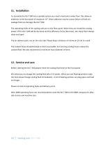
11. Installation To assembly the KG-T 500 into a spindle system you need a horizontal under-floor. We allow an addiction to the horizontal of maximum 10°. More addiction may be causes failure of fluid run. Leakage fluid can damage the KG-T 500. The aspirating holes of the cooling unit are on the floor panel. When they are closed the cooling power of the KG-T 500 will be decrease and the efficiency factor decreases, too. Keep them always clean and open. The air delivery ports are on the rear side. Please keep a distance of minimum 10 cm to a wall. The coolant hoses should be kept as short as possible....
Open the catalog to page 14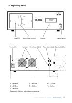
Power Switch Fluid Level Control C = 41,5mm Deepness = 340mm (without any connectors) …when it comes to quality! BMR GmbH
Open the catalog to page 15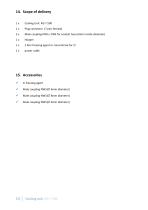
Plug connector (7 pins female) Male coupling NW5 / DN5 for coolant hose (6mm inside diameter) 2 liter freezing agent or concentrate for 2l power cable 15. Accessories 1l freezing agent Male coupling NW5(∅ 6mm diameter) Male coupling NW5(∅ 8mm diameter) Male coupling NW5(∅ 9mm diameter)
Open the catalog to page 16
MORE PRODUCTS OF BMR GMBH Sealing Air Follow-Up Control Nominal voltage: Start input voltage: Power consumption: Relay details: Accu: Als Option ist ein Fernsteuer-Adapter zum direkten Anschluss an das I/O Interface an der Stiftleiste SL2 verfügbar. On option a remote controller is available which can directly be connected with the I/O interface at SL2. By this, the required duty speed can be adjusted with a potentiometer and the converter can be started and stopped with a rocker switch. The status of the digital outputs is indicated on LEDs. The solution for monitoring and control of the sealing...
Open the catalog to page 17All BMR GmbH catalogs and technical brochures
 Catalogue
52 Pages
 SFU 0102
28 Pages
 SFU 400
15 Pages
 SFU 0102/0202
28 Pages
 SFU 0103/0203
30 Pages
 SFU 0303
56 Pages
 SFU0300
24 Pages
 SFU-ErrorFlags
7 Pages
 RS232 Control Commands
6 Pages
 SpindlecoolerKG-T 500
24 Pages
 DressView
32 Pages
 Folnet P S / P S 300
8 Pages
 Folnet P
8 Pages
 Folnet3-NT
8 Pages
 Folnet 1 NT
8 Pages
 Folnet 1
8 Pages
 Folinv 12/3
4 Pages
 SFU 0401
10 Pages
 SFU 0302 19”
28 Pages
 SFU 0302 SSE
30 Pages
 SFU 0101/0201
17 Pages
 SFU 0100
2 Pages
 SFU 0303/4
48 Pages
 SFU 0303/2
50 Pages
 SFU0052
12 Pages
 SFU 0200/1
24 Pages
 SFU 0103
24 Pages
 SFU 0156
20 Pages
 SFU 0150
20 Pages

- Measuring machine
- Automatic measurement system
- Frequency inverter
- Measuring system for industrial applications
- Compact frequency inverter
- Digital output frequency inverter
- IP20 frequency inverter
- Motor frequency converter
- Vector control frequency inverter
- LED driver
- Integration frequency inverter
- Fieldbus frequency inverter
- Induction frequency converter
- Cabinet frequency inverter
- Low-voltage frequency inverter
- Asynchronous motor frequency inverter
- Vector-controlled frequency inverter
- Digital display frequency inverter
- Panel frequency inverter
- Synchronous motor frequency inverter