- Catalogs
- BMC Messsysteme GmbH
- USB-PIO
USB-PIO
1 /8Pages

USB-PIO
1 /8Pages
Catalog excerpts
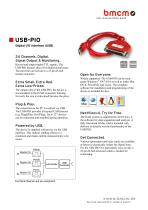
Digital I/O Interface (USB) Open for Everyone. 24 Channels. Digital. Signal Output & Monitoring. Record and output digital TTL signals. The USB-PIO features three 8-bit bidirectional ports. The port lines are led out to a 25-pin D-Sub female connector. Extra Small. Extra Red. Extra Low-Priced. The unique idea of the USB-PIO: the device is accomodated in the D-Sub connector housing. Not only the size is extra small but also the price. Plug & Play. The connection to the PC is realized via USB. The USB-PIO provides all typical USB features (e.g. Plug&Play, Hot-Plug). Up to 127 devices can be connected and installed during operation. Powered by USB. The device is supplied with power via the USB interface. This reduces cabling efforts to a minimum and makes mobile measurements a lot easier. Widely supported: The USB-PIO can be used under Windows® XP/7/8/10 as well as under Mac OS X, Free BSD, and Linux. The complete software for installation and programming of the device is included for free. NextView®4. Try for Free. The DAQ system is supported by NextView® 4, the software for data acquisition and analysis. A fully functional 30-day trial is included with delivery to directly test the functionality of the USB-PIO. Get Connected. Various optocoupler and relay cards are available at bmcm to electrically isolate the digital lines. For the USB-PIO it is particularly easy as only a 25-pin D-Sub extension cable is needed for connecting. bavarian measurement company munich
Open the catalog to page 1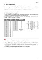
1 Start-up Procedure Install the bmcm driver package (see chapter 4.1.1). Connect the USB cable of the USB-PIO to the USB-interface of the PC and start the Plug&Play installation (see chapter 4.1.2). The device is supplied with power via the USB-connection. If necessary, further software components can be installed now, as described in chapter 0. 2 Digital Inputs and Outputs The USB-PIO features a ^-controller providing three 8-bit digital ports A, B, C. The lines are bidirectional. The direction is set to input or output in groups of 8 (port C: 4) via software. The following table and figure...
Open the catalog to page 2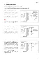
3 Interfacing Examples 3.1 Interfacing Examples for Digital Inputs The 3.9kQ pull-down resistor sets the input to low if no voltage is applied there. 3.1.1 Connecting an Optocoupler Optocouplers provide optimum protection at each input line. With them, it is possible to connect higher voltages and to protect the hardware from being destroyed. In this regard, please also see application examples of the optocoupler you use. O Optocoupler cards featuring 8 inputs are available at bmcm (see chapter 0). 3.1.2 Connecting a Push-Button / Switch Please make sure to use a push-button with debounce protection,...
Open the catalog to page 3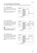
3.2 Interfacing Examples for Digital Outputs Serial resistors in the output lines limit the current and protect the hardware from being destroyed. 3.2.1 Connecting an LED Only so-called low-current LEDs can be used, because they already work with 1mA current. Please also observe the total current listed in the technical data (see chapter 7). Ausgang/ output Masse! Ground 3.2.2 Connecting a Relay A connected relay is ideal to switch higher currents. Since the field coil of the relay requires a higher current than provided by the measurement system at one line, a transistor is connected ahead....
Open the catalog to page 4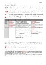
4 Software Installation All software and documentation available for the USB-PIO are integrated on the "Software Collection" CD included with delivery. When inserting the CD, a CD starter opens automatically (otherwise: start openhtml.exe). Change to the product page of the USB-PIO by selecting the entry "Products" in the CD starter and then the hardware ("USB-PIO") listed under the interface "USB". For detailed information about installing or operating the software, please see the corresponding manuals. The Adobe Acrobat Reader is required to open the documentation in PDF format. You can run...
Open the catalog to page 5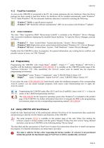
Plug&Play Installation As soon as the USB-PIO is connected to the PC, the system announces the new hardware. Since the driver package has been copied to hard disc before, the hardware will be installed automatically under Windows® 7/8/10. Under Windows® XP, the automatic hardware detection is started by selecting the following: - Windows® 7/8/10: no specifications required - Windows® XP: "Install the software automatically" (SP2: do not connect with Windows® Update!) Check Installation The entry "Data Acquisition (BMC Messsysteme GmbH)" is included in the Windows® Device Manager after successful...
Open the catalog to page 6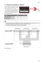
5 Connection Technology for USB-PIO bmcm provides optocoupler and relay cards to electrically isolate the digital inputs and outputs of the USB-PIO. The connectors are directly compatible for a 25-pin D-Sub standard cable to be used. If connecting several OR8, R8 to the USB-PIO, a special cable has to be made (see figure below). O • The port direction of the USB-PIO must comply with the settings of the optocoupler/relay card to avoid damages (optocoupler channels to input, relay channels to output). • For further information, please see the relevant data sheets.
Open the catalog to page 7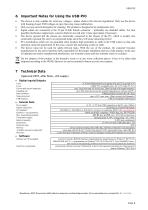
6 Important Notes for Using the USB-PIO • The device is only suitable for extra-low voltages - please observe the relevant regulations! Only use the device with housing closed. ESD voltages at open lines may cause malfunction. • Only use non-solvent detergents for cleaning. The product is designed to be maintenance-free. • Signal cables are connected at the 25-pin D-Sub female connector - preferably use shielded cables. For best possible interference suppression, connect shield at one end only. Close open inputs if necessary. • The device ground and the chassis are electrically connected to the...
Open the catalog to page 8All BMC Messsysteme GmbH catalogs and technical brochures
 MAL-PT100
4 Pages
 MAL-FU
4 Pages
 MAL-ISO Series
4 Pages
 LAN-AD16fx
12 Pages
 USB-AD16f
8 Pages
 USB-AD14f
8 Pages
 USB-AD
8 Pages
 AMS42-LAN16fx
12 Pages
 AMS42-USB
12 Pages
 AMS84-LAN16fx
12 Pages
 AMS84-USB
12 Pages
 PCIe-Base
12 Pages
 PCI-BaseII
12 Pages
 MADDA16n
4 Pages
 MDA16-4i
4 Pages
 MCAN
MCAN4 Pages
 USB-OI16
8 Pages
 USB-PIO-OEM
8 Pages
 PCI-PIO
8 Pages
 Amplifiers
24 Pages
 Data Acquisition
40 Pages
 Software
8 Pages
 Overview
2 Pages
Archived catalogs


- IO module
- Rectangular connector
- Digital IO module
- Signal amplifying integrated circuit
- Cable assembly
- Coaxial connector
- DIN rail mounted I O module
- Compact I/O
- Compact converter
- Data acquisition unit
- Industrial converter
- Communication interface card
- Measuring amplifier
- Voltage amplifier
- Industrial interface expansion card
- Compact IO module
- DC amplifier
- Electronic amplifier