- Catalogs
- BISHOP-WISECARVER
- Signature Motion SteadyRail Systems
Signature Motion SteadyRail Systems
1 /18Pages

Signature Motion SteadyRail Systems
1 /18Pages
Catalog excerpts

Expertly Designed, Delivered to Perform Signature Motion SteadyRail Systems Mechanical Automation Solutions Positioning Stages & Tables
Open the catalog to page 1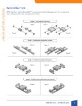
LINEAR MOTION SYSTEMS System Overview BWC Signature Motion SteadyRail™ is constructed of high quality aluminum alloy components and is protected with a clear anodized surface finish. Stage 1 - End Supported Systems Stage 2 - Continuously Supported Systems Stage 3 - Double End Supported Systems Stage 4 - Double Continuously Supported Systems
Open the catalog to page 3
LINEAR MOTION SYSTEMS Part Number System SteadyRail™ Linear Motion Systems (Formerly: LM Systems) 04 J CS Txx B Notes: Standard Travel Lengths: 06, 12, 18, 24, 30, 36, 42, 48 Type 1 and 2 use System Length (LXX), Type 3 and 4 use Travel Length (TXX)
Open the catalog to page 4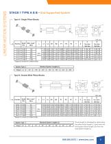
STAGE 1 TYPE A & B - End Supported System Type A / Single Pillow Blocks L1 Unit: inch * Based on a travel of 2 million inches. System Type Standard System Lengths (L) Stage 1 - B Travel length is calculated by subtracting the pillow block length (L1) and both the end support block length (L2) from the total system length (L).
Open the catalog to page 5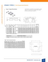
LINEAR MOTION SYSTEMS STAGE 1 TYPE C - End Supported System Type C / Single Pillow Blocks Travel length is calculated by subtracting the carriage length (L1) and both the end support block length (L2) from the total system length (L). Unit: inch
Open the catalog to page 6
LINEAR MOTION SYSTEMS STAGE 1 TYPE D - End Supported System Type D / Double Wide Pillow Blocks Travel length is calculated by subtracting the carriage length (L1) and both the end support block length (L2) from the total system length (L). Unit: inch
Open the catalog to page 7
LINEAR MOTION SYSTEMS STAGE 2 TYPE A & B - Continuously Supported System Type A / Single Pillow Blocks Unit: inch Travel length is calculated by sub-tracting the pillow block length (L1) from the total system length (L).
Open the catalog to page 8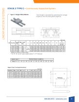
STAGE 2 TYPE C - Continuously Supported System Type C / Single Pillow Blocks Travel length is calculated by subtracting the carriage length (L1) from the total system length (L). Unit: inch Part No. Shaft Dia. Max. Load (lbs.) L1 D Thru Hole / Bolt Size
Open the catalog to page 9
STAGE 2 TYPE D - Continuously Supported System Type D / Double Wide Pillow Blocks Travel length is calculated by subtracting the carriage length (L1) from the total system length (L). Unit: inch Part No. Shaft Dia. Max. Load * (lbs.) L1 B1 B2 B3 D Thru Hole / Bolt Size
Open the catalog to page 10
LINEAR MOTION SYSTEMS STAGE 3 TYPE A - End Supported System Type A / Single Pillow Blocks Unit: inch * Based on a travel of 2 million inches. Unit: inch Travel Overall System Length (L)
Open the catalog to page 11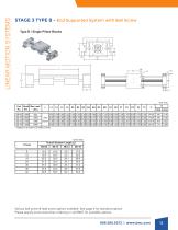
STAGE 3 TYPE B - End Supported System with Ball Screw Type B / Single Pillow Blocks Unit: inch * Based on a travel of 2 million inches. Unit: inch Travel Overall System Length (L) Various ball screw & lead screw options available. See page 4 for standard options Please specify screw lead when ordering or call BWC for available options.
Open the catalog to page 12
LINEAR MOTION SYSTEMS STAGE 4 TYPE A - Continuously Supported System Type A / Single Pillow Blocks Unit: inch * Based on a travel of 2 million inches. ** For 12", 24", and 36" travel lengths subtract 1" of "Y" dimension. Unit: inch Travel Overall System Length (L)
Open the catalog to page 13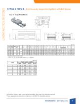
LINEAR MOTION SYSTEMS STAGE 4 TYPE B - Continuously Supported System with Ball ScrewType B / Single Pillow Blocks Unit: inch * Based on a travel of 2 million inches. ** For 12", 24", and 36" travel lengths subtract 1" of "Y" dimension. Unit: inch Travel Overall System Length (L) Various ball screw & lead screw options available. See page 4 for standard options Please specify screw lead when ordering or call BWC for available options.
Open the catalog to page 14
TECHNICAL GUIDE BASIC DYNAMIC LOAD (C ) This term is arrived at based upon evaluation of a number of identical linear systems individually run in the same conditions. 90% of them can run with the load (with a constant value in the constant direction) for a distance of 2,000,000 inches without damage caused by rolling fatigue. This is the basis of this rating. BASIC STATIC LOAD RATING (CO) This term defines a static load such that at the contracting position where the maximum stress is exercised, the sum of the permanent deformation of the rolling elements and that of the rolling plane is 0.0001...
Open the catalog to page 15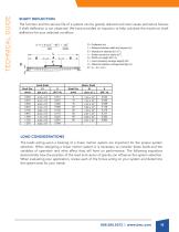
TECHNICAL GUIDE SHAFT DEFLECTION The function and the service life of a system can be greatly reduced and even cause premature failures if shaft deflection is not observed. We have provided an equation to help calculate the maximum shaft deflection for your selected condition. D = Deflection (in) L = Distance between shaft and support (in) E = Modulus of elasicity (lbf / in2 ) I = Shafts moment of inertia (in4 ) S = Shaft unit weight (lbf / in) F = Load (including carraige weight) (lbf) A = Distance between carriage bearings (in) B = (L - A) / 2 (in) LOAD CONSIDERATIONS The loads acting upon...
Open the catalog to page 16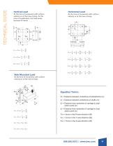
Vertical Load At the time of movement with uniform velocity or at the time of stop. At the time of acceleration, the load varies because of inertia. Side Mounted Load Horizontal Load At the time of movement with uniform velocity or at the time of stop. At the time of movement with uniform velocity or at the time of stop. Equation Terms: d0 = Distance between centerlines of pillowblocks (in) d1 = Distance between centerlines of shafts (in) d2 = Distance from centerline of carriage to load action point (in) F1X ~ F4X = d3 = Distance from centerline of carriage to load action point (in) FNX = force...
Open the catalog to page 17
Manufacturer of Linear Motion Systems & Components Mechanical Automation Solutions Outsource Manufacturing Integration Sub-Assemblies Systems Value Added Capabilities Multi-Line Supplier Order Online Download CAD Drawings CONTACT US 2104 Martin Way / Pittsburg, CA 94565 Phone 888.580.8272 www.bwc.com / [email protected] Twitter: @BWCnews GROUP BishopWisecarver A FAMILY OF SOLUTIONS
Open the catalog to page 18All BISHOP-WISECARVER catalogs and technical brochures
 PSD80
PSD8012 Pages
 PSD120
8 Pages
 DAPDU2
2 Pages
 EconoMotion®
2 Pages
 DTS
DTS12 Pages
 DualVee
48 Pages
 HepcoMotion® GV3
56 Pages
 HDS2
HDS252 Pages
 HDLS
HDLS16 Pages
 HDRT
HDRT24 Pages
 HTS
HTS38 Pages
 MadeWell
12 Pages
 PDU 2
PDU 22 Pages
 HepcoMotion ® PDU2M
4 Pages
 HepcoMotion
12 Pages
 SL2
SL228 Pages
 UtiliTrak Series
64 Pages
 INNOVATION IS EVOLUTIONARY
3 Pages
 Signature Motion ECO60
3 Pages
 Signature Motion SlickStick
3 Pages
 MadeWell®
2 Pages
 DTS Driven Track System
12 Pages
 UtiliTrak® Linear Motion Guide
16 Pages
 QuickSelect Guide
44 Pages


Archived catalogs
 GV3 Linear Guidance
56 Pages
 DualVee Motion Technology
32 Pages
 PDU2 Profile Driven Unit
2 Pages
 DLS Driven Linear System
28 Pages
 MinVee Catalog
4 Pages

- Lumibird actuator
- Industrial robot
- Linear actuator
- Lumibird electric actuator
- Lumibird linear positioning stage
- Floor-mounted robot
- Motorized positioning table
- Lumibird compact actuator
- Lumibird precision positioning stage
- Lumibird screw actuator
- Lumibird linear guide
- Lumibird precision actuator
- Lumibird 1-axis positioning stage
- Welding robot
- Lumibird linear axis
- Lumibird aluminum actuator
- Motorized actuator
- Lumibird ball screw actuator
- Double-acting actuator