- Catalogs
- BISHOP-WISECARVER
- DTS Driven Track System
DTS Driven Track System
1 /12Pages

DTS Driven Track System
1 /12Pages
Catalog excerpts
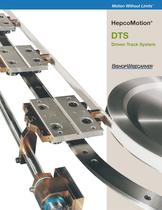
Motion Without Limits TM DTS Driven Track System Motion Without Limits ® HepcoMotion®
Open the catalog to page 1
Complementary to the Hepco Ring Slides & Track System*, the DTS is a ready-assembled unit providing a facility to drive Hepco carriages around a Hepco Track circuit under either continuous or intermittent motion. At all times the carriages are rigidly guided along the precision track and can thus maintain accurate alignment and resist deflection from external loads. The carriages are usually positioned at equal pitches as specified by the customer and are connected to a high strength timing belt. Aware that customer’s integrated equipment could be damaged in the event of a jam, an ingenious Trip...
Open the catalog to page 2
System Composition Pulley Bearing Units - with sealed bearing cartridges can be adjusted to provide tension for the belt. The bearings are ‘greased for life’. Any one of the pulley bearing units may be specified as the drive unit, which will then incorporate a 25 mm diameter plain shaft extension for motor mounting or for the attachment of other power sources. More than one drive unit per system may be specified. Drive pulleys have teeth, idler pulleys are plain. The drive motor may be selected from a range of compatible AC Geared Motors supplied by Bishop-Wisecarver. Alternatively, customers...
Open the catalog to page 3
Applications Typical Applications Continuous Motion: Due to the predictable path and high stiffness of the Hepco DTS, it is possible to perform accurate tasks on the move in precise registration with other mechanisms. Performing tasks on the move enables slow processes to be carried out at a fast rate. Work can be carried out on the periphery of a product by designing the circuit to mimic the product shape. The Hepco DTS is therefore the ideal choice for applications such as: High Speed: LETTER SORTING LABELLING DEVELOPING PRINTING ADHESIVE APPLICATION PACKAGING LAMINATING GLASS CUTTING PAINT...
Open the catalog to page 4
Applications Application Example Optical Lens Assembly Lenses are loaded by pick and place units onto clamp fixtures mounted on each carriage. The top carriages are accurately located using the Hepco Carriage Locking System. Optical adhesive is applied between the lenses, which then pass through an ultra violet light box to activate the hardener. The lenses are finally inspected for optical clarity and then released onto an accept or reject conveyor. On the return, the empty fixtures are brushed clean. The vertical orientation of the system allows excess adhesive to drip onto a collector and...
Open the catalog to page 5
411102910602010119ø25198.5351Belt adjustmenton all pulleysSection X – XSpacerSpacerDrive Shaft156.528.5244175.5205.5Rectangular circuit W min = 250Oval circuit L min = 25045°120XX4 ShaftCarriage 450672612Y105Carriage spacing 110 min4 X M6 mounting holesSection - 132 tooth AT10Circumference = 1320mmPulley 612DTS – 25 – 35115012585 Data & Dimensions 5 For Carriage Locking
Open the catalog to page 6
4 X M8 mounting holes Carriage spacing 160 min 392 336 306 10 128 38 14 115 197 45° Rectangular circuit W min = 450 Oval circuit L min = 450 672 612 Y Section Y – Y Pulley - 60 tooth AT10 Circumference = 600mm DTS – 44 – 612 150 125 Data & Dimensions 6 System see page 9
Open the catalog to page 7
Selection and Specification Specifying system parameters 1 Specify dynamic parameters Carriage load. External forces. Full velocity profile including accelerations, dwells, speeds, duty cycle and required life. 2 Make an initial selection Consider the physical size and weight of the component to be carried and make an initial selection of system size. Parts mounted to the carriage can overhang the sides as the design allows clearance. As a guide to weights a size 25 carriage would typically be used up to 20 kg with 40 kg being usual for size 44. Both systems can carry higher loads than this (see...
Open the catalog to page 8
Selection and Specification Additional sizes and more detailed information can be found in the DLS (Driven Linear Transmission and Positioning System). Note that considerably higher linear forces can be achieved by incorporating more than one drive unit utilizing geared motors of the WG7 design. This configuration gives the advantage of sharing the drive load between pulley bearing units. Alternatively, Bishop-Wisecarver can supply the DTS drive unit shaft(s) prepared to receive the customer’s drive source. 8 Nominal Linear Working Nominal Linear Motor Power Motor Type Gearbox Ratio Gearbox Rated...
Open the catalog to page 9
952910580BABA50150DTS – 44DTS – 25115801060100716061Locking AssemblySection A – ACylinder AssemblySection B – BCarriage spacing 110 min30 min to pulley CLBA891080381146011866060Cylinder AssemblySection B – BLocking AssemblySection A – ABA50Carriage spacing 160 min40 min to pulley CL24 Optional Equipment 9 Carriage Locking System Specify the stations on the circuit where you require carriages to be locked in position.
Open the catalog to page 10
Optional Equipment 10 SUBMIT DATA REQUIRED (PAGES 7 TO 10) AND YOU WILL RECEIVE YOUR SYSTEM LAYOUT Operational Safety Since the DTS is a mechanism which forms part of a larger machine a CE mark is not required, but each unit is supplied with a Declaration of Incorporation which will enable the machine builder to include it as part of the CE marking criteria for his complete machine. The operating instructions, mechanical guarding and electrical safety are the responsibility of the user incorporating the DTS into their machine, and these should be designed in line with the requirements outlined...
Open the catalog to page 11
Bishop-Wisecarver Corporation: Manufacturer of the original DualVee® guide wheel and industry leader in guided motion technology, and exclusive North and Central American partner and distributor for HepcoMotion products since 1984. Bishop-Wisecarver DualVee® Guide Wheels LoPro® Linear Motion System MadeWell® Crown Rollers MinVee® Linear Slide System UtiliTrak® Linear Motion Guide HepcoMotion® DAPDU2 Double Acting Profile Driven Unit DLS Driven Linear System DTS Driven Track System GV3 Linear Guidance and Transmission System HDCB Heavy Duty Compact Beam HDCS Heavy Duty Compact Screw HDLS Heavy...
Open the catalog to page 12All BISHOP-WISECARVER catalogs and technical brochures
 PSD80
PSD8012 Pages
 PSD120
8 Pages
 DAPDU2
2 Pages
 EconoMotion®
2 Pages
 DTS
DTS12 Pages
 DualVee
48 Pages
 HepcoMotion® GV3
56 Pages
 HDS2
HDS252 Pages
 HDLS
HDLS16 Pages
 HDRT
HDRT24 Pages
 HTS
HTS38 Pages
 MadeWell
12 Pages
 PDU 2
PDU 22 Pages
 HepcoMotion ® PDU2M
4 Pages
 HepcoMotion
12 Pages
 SL2
SL228 Pages
 UtiliTrak Series
64 Pages
 INNOVATION IS EVOLUTIONARY
3 Pages
 Signature Motion ECO60
3 Pages
 Signature Motion SlickStick
3 Pages
 MadeWell®
2 Pages
 UtiliTrak® Linear Motion Guide
16 Pages
 QuickSelect Guide
44 Pages


Archived catalogs
 GV3 Linear Guidance
56 Pages
 DualVee Motion Technology
32 Pages
 PDU2 Profile Driven Unit
2 Pages
 DLS Driven Linear System
28 Pages
 MinVee Catalog
4 Pages

- Lumibird actuator
- Industrial robot
- Linear actuator
- Lumibird electric actuator
- Lumibird positioning stage
- Lumibird linear positioning stage
- Floor-mounted robot
- Motorized positioning table
- Lumibird compact actuator
- Lumibird precision positioning stage
- Lumibird screw actuator
- Lumibird linear guide
- Lumibird precision actuator
- Lumibird 1-axis positioning stage
- Welding robot
- Lumibird linear axis
- Lumibird aluminum actuator
- Motorized actuator
- Lumibird ball screw actuator
- Double-acting actuator