- Catalogs
- BISHOP-WISECARVER
- DLS Driven Linear System
DLS Driven Linear System

DLS Driven Linear System
The document provides comprehensive details on the Driven Linear System (DLS) by HepcoMotion, distributed by Bishop-Wisecarver. It includes information on various linear motion systems and components such as DualVee Guide Wheels and LoPro Linear Motion System.
The DLS addresses linear drive challenges with components like carriages, toothed belt drives, and rigid aluminum beams. Features include tapped holes for component fixing, removable platforms for machining, and integral belt tensioners.
Applications include multi-axis systems for X-Y-Z movements, with the cantilever axis suitable for Z-axis or horizontal pick-and-place applications.
Detailed dimensions and data for components such as standard and cantilever axes, AC geared motors, and gearboxes are provided, including load capacities and beam lengths.
Guidance is offered on selecting the appropriate system based on application requirements, including system accuracy and repeatability.
This section covers slide load, life, deflection, and linear drive calculations, providing technical specifications for optimal performance.
Instructions for ordering DLS3 and DLS4 systems are provided, detailing beam lengths, drive input types, and output shaft options.
Bishop-Wisecarver offers additional components like precision planetary gearboxes and worm gearboxes, along with fixing clamps and T nuts for securing the system.
The DLS range offers a comprehensive solution for linear motion applications, compatible with various motors and control systems. Bishop-Wisecarver supports custom applications and provides a CAD CD for detailed drawings.
- Motors: Geared AC induction motors with power from 60W to 1.8kW, protected to IP54, including braked versions with failsafe electro-mechanical brakes.
- AC Motor Drive: Utilizes Allen-Bradley Rockwell Automation Smart Speed Controllers, suitable for output power ratings from 0.37 to 1.5kW, featuring a programming keypad and fault diagnostics.
- System Composition: Includes configurations such as X-Y and X-Y-Z systems, with options for high precision planetary gearboxes and worm gearboxes.
- Sheet Feeding Mechanism: Uses DLS for feeding sheets in a vacuum moulding process, controlled by a PLC.
- Cable Twisting Machine: Employs DLS for making twisted cables, with a servo motor and programmable drive/positioner.
- Waste Metal Picker: Utilizes a DLS cantilever axis for removing waste metal from injection moulding machines.
- X-Z Transfer Unit: Automated system for moving components to a cleaning tank, using a DLS3 unit and cantilever axis.
- For vertical applications or where load back-driving is a concern, use brake motors.
- Consider using a single inverter drive for cost efficiency when X and Z-axis motions do not occur simultaneously.
- Gearbox Options: Available in ratios from 5:1 to 75:1, with efficiencies between 75-90% depending on speed and ratio.
- Motor Dimensions: Motors available in 4 IEC frame sizes, with options for short or long field windings and 2 or 4 pole designs.
Detailed specifications for various gearbox models, including their use, ratio, output torque, inertia, maximum input speed, shaft diameter, backlash, efficiency, dimensions, weight, and maximum motor weight are provided.
The DLS3C model is highlighted for its dimensions and compatibility with AC geared motors and planetary gearboxes, using lightweight beams for reduced moving mass and options for increased stiffness.
Details on fixing clamps for securing DLS beams and the importance of drive shafts for connecting parallel DLS axes are provided, emphasizing support bearings in high-speed applications to prevent shaft whipping.
The lightweight beam is described as half the weight of the standard version, beneficial for systems where the beam moves, maintaining the same external dimensions but less stiff, which may increase deflection in long spans.
The document outlines a method for selecting the right DLS and AC geared motor combination based on load, linear force, bending strength, and physical dimensions.
Options for brake motors, torque limiters, and motor configurations are discussed, advising on selecting motors with enhanced IP ratings and special finishes for specific applications.
The Allen-Bradley Bulletin 160 Smart Speed Controller allows programmable speed and acceleration control for AC geared motors, offering different models for speed selection.
For arduous applications, select combinations with the highest gearbox rated linear force, and consult Bishop-Wisecarver for precise ratings in unusual cases.
The system is designed to minimize electromagnetic interference and comply with the EU EMC directive, including a separate line filter and an optional dynamic braking module for applications requiring dynamic braking.
Configurations using the Allen-Bradley Smart Speed Controller for simple applications are described, including a circuit diagram for control inputs and outputs.
The DLS system lacks position measurement or feedback, relying on switches for positioning, with suggestions for improving accuracy.
Recommendations include ensuring system reliability and safety by preventing motion beyond prescribed boundaries and providing emergency stop facilities.
Formulas for calculating the life of a DLS unit based on load factors are provided, including an example calculation.
This section covers the calculation of system deflection, including beam and carriage deflection, providing equations for beam bending and deflection under various conditions.
Methods for determining the performance of a HepcoMotion® DLS with a custom motor and gearbox are provided, including key parameters like motor moment of inertia and gearbox efficiency.
Details the ordering process for DLS3 and DLS4 units, including options for beam length, carriage length, drive input and output types, and lightweight options.
The DLS5 unit is built on a strong aluminum beam with a GV3 slide, driven by a timing belt and pulley, supporting high loads and speeds.
An example involves using DLS5 units to move large sheets of material from a process line to a storage pallet, suitable for dirty environments due to the Vee slide design.
'K' indicates a keyed output shaft, while '0' indicates no shaft. Input handling is denoted by 'R' or 'L', indicating the drive input on the right or left-hand side.
Customers seeking further details on optional geared motors or gearbox fitting kits are advised to contact Bishop-Wisecarver.
A table shows the maximum loading for the carriage in each possible loading mode, serving as a guide for initial selection.
The document mentions load capacities but does not provide specific values, assuming one shaft with no gearbox.
Various linear motion systems and components offered by Bishop-Wisecarver are listed, including DualVee® Guide Wheels and LoPro® Linear Motion System.
Bishop-Wisecarver is noted as the manufacturer of the original DualVee® guide wheel and a leader in guided motion technology.
Bishop-Wisecarver provides a one-year limited warranty ensuring products conform to published specifications and are free from defects.
For product orders and specific length requirements, customers are encouraged to contact Bishop-Wisecarver directly.
Catalog excerpts

HepcoMotion CONTENTS Page DLS3 and 4 . . . . . . . . . . . . . . . . . . . . . . . . . . . . . . . . . . . . 1System Composition . . . . . . . . . . . . . . . . . . . . . . . . . . . . . . . . . . . . . . . 2-4 Application Examples . . . . . . . . . . . . . . . . . . . . . . . . . . . . . . . . . . . . . . 5-7 Data & Dimensions . . . . . . . . . . . . . . . . . . . . . . . . . . . . . . . . . . . . . . . . 8-12 Standard Axis . . . . . . . . . . . . . . . . . . . . . . . . . . . . . . . . . . . . . . . . . . 8 AC Geared Motors & Gearboxes . . . . . . . . . . . . . . . . . . . . . . . . . . . 9...
Open the catalog to page 2
To satisfy increasing customer requirements, Hepco has upgraded its popular DLS range of linear transmissions.A new range of cost effective, high quality AC geared motors and worm gearboxes has been added to create a complete linear drive solution which is ideally suited to many positioning applications. Motors up to 1.1kW are offered as are gearboxes with ratios from 5:1 to 75:1. This provides driving forces to 1225N and linear speeds from zero to 2m/s (up to 5+m/s for systems using special motors). The reduced engineering package gives the power, flexibility and reliability of an electrical...
Open the catalog to page 3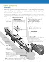
Brush SealsHigh Energy Absorbing BumperIdler End Box Optional output shaft > Rigid Aluminum Beam Up to 8m in one piece - longer with jointsՕ Lightweight option available on DLS3 Strong sections span wide gaps Օ Can be used as construction element of machine The HepcoMotion > DLS provides the complete solution to linear drive problems. It has been engineered with all the options required to enable it to handle almost any linear positioning application. The illustration below shows a unit with a fitted AC geared brake motor, which also has the optional output shaft (to enable direct coupling to...
Open the catalog to page 4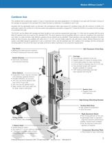
The cantilever axis is particularly useful in Z-axis or horizontal pick and place applications. It is intended to be used with the beam moving on the carriage, as opposed to the standard DLS where the beam is stationary. It is available in size 3 only.Supplied with the lightweight beam as standard, this arrangement offers rigid support for cantilever loads with the minimum of inertia. It is particularly useful in the context of a multi-axis system (see application examples on pages 6 & 7) where the DLS3C is mounted onto the carriage of a standard DLS axis.The DLS3C can be offered with carriage...
Open the catalog to page 5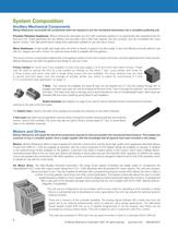
Bishop-Wisecarver can provide the components which are required to turn the mechanical transmission into a complete positioning unit. Precision Planetary Gearboxes. Bishop-Wisecarver will supply any DLS with a planetary gearbox in an appropriate ratio engineered into the drive end unit. These gearboxes are very efficient and accurate, have a high load capacity, are very compact, and are compatible with many electric motors. Their high performance makes them particularly suitable for use with servo motors. Worm Gearboxes . A high quality right angle drive unit which is directly coupled to the...
Open the catalog to page 6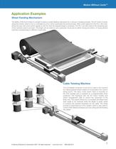
The ability of the DLS to feed to a length is used in a sheet feeding mechanism for a vacuum moulding process. The AC motor is driven using the inverter, which in turn is controlled by a PLC which supervises the whole process. After a start signal from the PLC, the motor drives the axis until a limit switch signals to the PLC that the required length is achieved. The PLC can then instruct the remaining part of the machine cycle to proceed. The length can be varied to suit a particular mould size by either moving the switch, or having several switches corresponding to different mould tools. >...
Open the catalog to page 7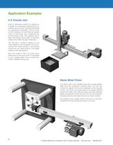
Used in automated system for picking up a basket of components, placing them in a cleaning tank and then returning the basket for subsequent processing. This unit uses a DLS3 standard unit with fitted AC geared motor for the X-axis, and a cantilever axis for the vertical Z-axis. The cantilever axis is fitted with a brake motor option to provide a holding force while this axis is stationary. The unit has a number of stations on the X-axis defined by limit switches, and a PLC controls the whole process, commanding moves from any starting point to the target position in the cleaning tank. Since...
Open the catalog to page 8
Motion Without Limits > The master X-axis transmission is shown fitted with a high precision planetary gearbox and a servo motor. It is connected to the slave X-axis by a transmission shaft connecting between the output shaft of the first X-axis and the input shaft of the second X-axis by flexible couplings. The Y-axis transmission also has the same motor and gearbox arrangement fitted. It is connected to the carriages of the X-axes using the long fixing clamps which fit directly onto the carriage plate mounting holes. Both master X-axis and the Y-axis have a switch cam on the carriage and a...
Open the catalog to page 9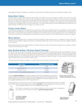
Having selected the right motor/gearbox combination, the user should then evaluate if any options are required for the geared motor: > The brake lining is spring loaded against the friction plate, so the brake coil must be energized to release. In the event of a power failure, the brake is applied, so the unit is fail safe. The brake fits under an extended fan cowling on the end of the motor. Dimensions are shown on page 9. The brake requires nominal 200-230V AC power (which is rectified for the DC coil). This means that the brake should not be connected in parallel with a motor phase if the...
Open the catalog to page 17
m ally Open Mo m entary Contact Nor m ally Closed Mo m entary Contact Rotary Potent i o m eter Forward i elded Cable TB3 Ter mi nal S i gnal Spec i f i cat i on Nor 1 +10V Pot 10k Potent i o m eter 2 Watts 2 Pot W i per Controller i nput im pendance = 100k 3 Co mm on Co mm on 4 4-20 m A Input Controller im pedance = 250 5 Reverse Contact closure i nput 6 Start Contact closure i nput 7 Co mm on Co mm on 8 Stop Contact closure i nput requ i red to operate controller 9 Nor m ally Closed Custo m er progra mm able relay outputs 10 Relay Co mm on Res i st i ve load 0 . 4A at 125VAC, 2A at 30VDC 11...
Open the catalog to page 18All BISHOP-WISECARVER catalogs and technical brochures
 PSD80
PSD8012 Pages
 PSD120
8 Pages
 DAPDU2
2 Pages
 EconoMotion®
2 Pages
 DTS
DTS12 Pages
 DualVee
48 Pages
 HepcoMotion® GV3
56 Pages
 HDS2
HDS252 Pages
 HDLS
HDLS16 Pages
 HDRT
HDRT24 Pages
 HTS
HTS38 Pages
 MadeWell
12 Pages
 PDU 2
PDU 22 Pages
 HepcoMotion ® PDU2M
4 Pages
 HepcoMotion
12 Pages
 SL2
SL228 Pages
 UtiliTrak Series
64 Pages
 INNOVATION IS EVOLUTIONARY
3 Pages
 Signature Motion ECO60
3 Pages
 Signature Motion SlickStick
3 Pages
 MadeWell®
2 Pages
 DTS Driven Track System
12 Pages
 UtiliTrak® Linear Motion Guide
16 Pages
 QuickSelect Guide
44 Pages


Archived catalogs
 GV3 Linear Guidance
56 Pages
 DualVee Motion Technology
32 Pages
 PDU2 Profile Driven Unit
2 Pages
 MinVee Catalog
4 Pages

- Lumibird actuator
- Industrial robot
- Linear actuator
- Lumibird electric actuator
- Lumibird positioning stage
- Lumibird linear positioning stage
- Floor-mounted robot
- Motorized positioning table
- Lumibird compact actuator
- Lumibird precision positioning stage
- Lumibird screw actuator
- Lumibird linear guide
- Lumibird precision actuator
- Lumibird 1-axis positioning stage
- Welding robot
- Lumibird linear axis
- Lumibird aluminum actuator
- Motorized actuator
- Lumibird ball screw actuator
- Double-acting actuator