3D Angled Mounting Adaptor
1 /2Pages

3D Angled Mounting Adaptor
1 /2Pages
Catalog excerpts
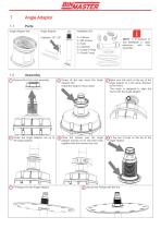
Angle Adaptor Angle Adaptor: 2 x Clamps 2 x M8 screws 2 x Nuts 2 x washers 2 x Large O-rings 1 x Small O-ring NOTE: It is advised to use BinMaster 2’ cable with this extension assembly. 1 Remove Nut from horn assembly 2 Screw all the way down the Angle Adaptor Nut Install the large O-ring in place 3 Make sure the notch at the top of the angle adaptor is in the same direction as the horns The notch is designed to align the horns with the angle adaptor. 4 Screw the Angle Adaptor nut up to the angle adaptor 5 Place the clamps over the angle adaptor and the nut to lock them both together with the screws and nuts 6 Fit the two O-rings on the top of the angle adaptor 7 Fit flange over the Angle Adaptor 8 Secure the Flange with the Nu
Open the catalog to page 1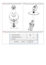
9 Insert the assembled Scanner (with flange mounted) into the vessel and direct the scanner to the center of the vessel Mount the Scanner’s head over the Angle Adaptor, see 3DLevelScanner Installation Manual for further information Towards Center of Vessel 11 Following successful installation connect the 3DLevelScanner to the 3DLevelManager and configure the Angle Adaptor field (under DeviceAdvanced Parameters…) according to the actual installation, note that the angle can be between 0° to
Open the catalog to page 2All BinMaster catalogs and technical brochures
 Capacitance Probe Brochure
12 Pages
 FeedView brochure
4 Pages
 CNCR-400 Brochure
2 Pages
 BMRX-300 Brochure
4 Pages
 Full Line Brochure
24 Pages
 NCR-86 Full Line Brochure
8 Pages
 SmartSonic Brochure
8 Pages
 Mini Rotary Brochure
2 Pages
 DPM-100 Display Brochure
2 Pages
 DPM-200 Display Brochure
2 Pages
 FVL-200 Brochure
4 Pages
 SPL-200 Brochure
4 Pages
 Tilt Switch Brochure
2 Pages
 C-100 Display Brochure
2 Pages
 BMRX-100 Basic Rotary
2 Pages
 BMRX-200 Brochure
2 Pages
 GWR-3000 brochure
2 Pages
 Vibrating Rod - 90
2 Pages
 Vibrating Fork brochure
2 Pages
 Airbrator
2 Pages
 GWR-2000 Guided Wave Radar
4 Pages
 Flow Detect 2000
2 Pages
 Rotary Product Line Brochure
8 Pages
 Vibrating Rod 90
2 Pages
 ProCap HD Brochure
1 Page
 Capacitance 101
2 Pages
 BinMaster DPM-300
8 Pages
 Adjustable Rotary
1 Page
 MultiBob System Brochure
8 Pages
 CVR-600 Mini Vibrating Rod
2 Pages


Archived catalogs
 3DLevelScanner
8 Pages
 Airpad
2 Pages
 Diaphragm Switch Brochure
2 Pages
 Full Line Product Catalog
24 Pages
 WL 19
WL 193 Pages
 WT 19
WT 193 Pages
 3D Technical Data Brochure
4 Pages
 COMPACTPRO Brochure
2 Pages
 SmartBob2 MUCM Brochure
2 Pages
 Mini-Rotary Brochure
2 Pages
 Get the Point
7 Pages
 DPM-100
8 Pages
 BinMaster DPM-200
6 Pages
 Digital Panel Meter Display
8 Pages
 Mini Vibrating Rod
2 Pages
 SmartBobII MUCM Brochure
2 Pages
 DPM-200 Digital Panel Meter
6 Pages
 Vibrating Fork 95
2 Pages
 Binventory Software Brochure
4 Pages
 NCR-84
4 Pages
 NCR-25 & NCR-30 Brochure
4 Pages
 NCR-80 Accessories Brochure
3 Pages
 Dust Detect 1000 Brochure
2 Pages
 VR-0515-NPC
4 Pages
 Full Line Catalog
24 Pages
 CNCR Non-Contact Radar
12 Pages
 MND Modbus Network Display
3 Pages
 3D MultiVision Software
4 Pages
 BinMaster Rotary Brochure
8 Pages
 NCR-80 Options Brochure
3 Pages
 Mercury_Free Tilt Switch
2 Pages
 BinMaster Air Pad Brochure
2 Pages
 NCR-80 Non-Contact Radar
4 Pages
 BinMaster Rotary brochure
8 Pages
 Diffuser Air Pad Brochure
2 Pages


- Liebherr measuring instrument
- Liebherr management software
- Liebherr automation software
- Liebherr level switch
- Liebherr Windows software
- Liebherr real-time software
- Liebherr cloud software
- Liebherr control software
- Liebherr liquid level switch
- Liebherr level sensor
- Liebherr liquid level sensor
- Liebherr digital indicator
- Liebherr monitoring software
- 3D software solution
- Liebherr interface software
- Liebherr measurement software
- Liebherr analog level sensor
- Liebherr automated software
- Liebherr digital measuring instrument
- Liebherr stainless steel level switch