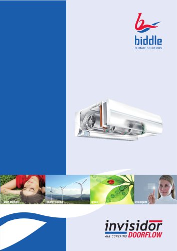
Catalog excerpts

CLIMATE SOLUTIONS Cassette units Model Comfort Circle
Open the catalog to page 1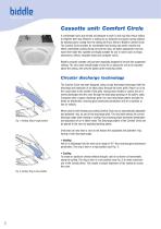
Cassette unit: Comfort Circle A comfortable room and climate are pleasant to work in and may also entice visitors to lengthen their stay. Whoever is looking for an attractive and space-saving solution for heating and/or cooling from the ceiling will find a friend in Biddle's Comfort Circle. The Comfort Circle provides for comfortable heat during cold winter months and offers comfortable cooling during hot summer days. Its stylish appearance and low noise level make this cassette unit highly suitable for use in rooms such as shops, showrooms, offices, reception areas and computer rooms....
Open the catalog to page 2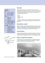
Variants Type codes CC 60-H1C2-M1 Type 60 = 60 x 60 cm recirculation 90 = 90 x 90 cm recirculation 60 V = 60 x 60 cm ventilation 90 V = 90 x 90 cm ventilation Coil type H2 = heating 2-row H3 = heating 3-row C2 = cooling 2-row C3 = cooling 3-row H1/C2 = heating 1-row/cooling 2-row R2 = cooling (direct expansion) 2-row R3 = cooling (direct expansion) 3-row H1/R2 = heating 1-row/cooling (direct expansion) 2-row Regulation S0 = standard air-side control S1 = standard air-side control with automatic angle adjustment M0 = modulating air- and water-side control M1 = modulating air- and water-side...
Open the catalog to page 3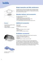
Simple inspection and little maintenance The inside of the unit is easy to access through the grille. A dirty filter may lead to inadequate performance as well as an increase in noise level. Therefore, the filter must be cleaned regularly. The air filter (Class G1) is located behind the inlet and is easy to clean using a vacuum cleaner. Standard delivery and accessories The Comfort Circle comes standard with: • 2 suspension profiles • 2 blanking plates to adjust the discharge pattern • integrated condensate discharge pump (only with cooling) • external condensate drain tray (only with...
Open the catalog to page 4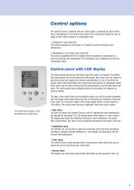
Control options The Comfort Circle is available with two control types: a standard (air-side) control and a modulating (air- and water-side) control. The control panel allows the user to easily set the indoor climate to a comfortable level. 1. Standard air-side control (S) This control regulates the fan speed (in 3 speed) to reach the desired room temperature. 2. Modulating air- and water-side control (M) This control regulates both the fan speed and the discharge air temperature to reach the desired room temperature. The ventilation unit is available only with this modulating control....
Open the catalog to page 5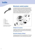
Electronic control system The control panel and the PCB in the unit constitute the electronic control system. The two components are connected to one another using a low-voltage cable that has RJ11 plugs. The side of the cassette unit houses a connector plate, where all connections are made. Here, the controller and other units, if any, are plugged in. Also, any waterside controls and in- and outputs can be connected here. The outputs (max. 24V) can be used for, for instance, controlling the CH boiler or cooling units. Faults can be reported, too. To the input, a low-limit thermostat, a...
Open the catalog to page 6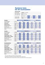
Technical data CC 60 recirculation General data supply voltage max. current cons. max. power input tapping voltage sound pressure Heating air inlet conditions1 tapping voltage air flow rate heating capacity discharge temperature2 water flow rate water-side pressure loss3 weight Cooling air inlet conditions1 tapping voltage air flow rate cooling capacity - total cooling capacitiy - sensible discharge temperature2 water flow rate water-side pressure loss3 weight Heating/Cooling air inlet conditions1 tapping voltage air flow rate heating capacity cooling capacity - total cooling capacity -...
Open the catalog to page 7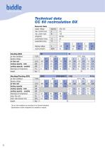
Technical data CC 60 recirculation DX General data supply voltage max. current cons. max. power input refrigerant condensation temp. evaporation temp. tapping voltage sound pressure Cooling (DX) air inlet conditions1 tapping voltage air flow rate cooling capacity - total cooling capacaty - sensible discharge air temperature weight Heating/Cooling (DX) air inlet conditions1 tapping voltage air flow rate heating capacity cooling capacity - total cooling capacity - sensible discharge air temperature water flow rate water-side pressure loss weight 1 2 The air inlet conditions are according to...
Open the catalog to page 8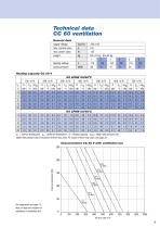
Technical data CC 60 ventilation General data supply voltage max. current cons. max. power input weight tapping voltage sound pressure tLi = Inlet air temperature tLu = Outlet air temperature Q = Heating capacity Δpw = Water-side pressure loss Water-side pressure loss is exclusive of three-way valve. For values of three-way valve, see page 20. Characteristics CC 60 V with ventilation box 250 50 For explanation see page 13. Note: all data are inclusive of resistance in ventilation box.
Open the catalog to page 9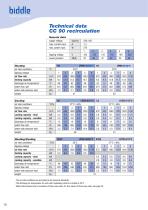
Technical data CC 90 recirculation General data supply voltage max. current cons. max. power input tapping voltage sound pressure Heating air inlet conditions1 tapping voltage air flow rate heating capacity discharge air temperature2 water flow rate water-side pressure loss3 weight Cooling air inlet conditions1 tapping voltage air flow rate cooling capacity - total cooling capacity - sensible discharge air temperature2 water flow rate water-side pressure loss3 weight Heating/Cooling air inlet conditions1 tapping voltage air flow rate heating capacity cooling capacity - total cooling...
Open the catalog to page 10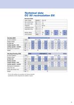
Technical data CC 90 recirculation DX General data supply voltage max. current cons. max. power input refrigerant condensation temp. evaporation temp. tapping voltage sound pressure Cooling (DX) air inlet conditions1 tapping voltage air flow rate cooling capacity - total cooling capacity - sensible discharge air temperature weight Heating/Cooling (DX) air inlet conditions1 tapping voltage air flow rate heating capacity cooling capacity - total cooling capacity - sensible discharge air temperature water flow rate water-side pressure loss weight 1 2 The air inlet conditions are according to...
Open the catalog to page 11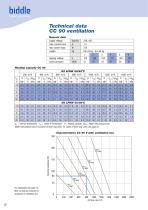
Technical data CC 90 ventilation General data supply voltage max. current cons. max. power input weight tapping voltage sound pressure tLi = Inlet air temperature tLu = Outlet air temperature Q = Heating capacity Δpw = Water-side pressure loss Water-side pressure loss is exclusive of three-way valve. For values of three-way valve, see page 20. Characteristics CC 90 V with ventilation box 250 50 For explanation see page 13. Note: all data are inclusive of resistance in ventilation box.
Open the catalog to page 12All Biddle catalogs and technical brochures
-
INDAC2
32 Pages
-
INVISIDOR STYLE
8 Pages
-
DX AIR CURTAIN
28 Pages
-
SENSAIR
52 Pages
-
Model DECO
28 Pages
-
Model NOZ
20 Pages
-
Model MAT
8 Pages
-
Model DoorFlow
16 Pages
-
Model CITY
12 Pages
-
Model CA2 / CA2VQ
20 Pages
-
Model IndAC
20 Pages
-
VRV heat recovery:CA2V
8 Pages
-
Invisidor CA2
20 Pages
-
Invisidor DoorFlow
16 Pages
Archived catalogs
-
Invisidor CITY
12 Pages
-
Invisidor STYLE
8 Pages
-
Product range overview
16 Pages
-
Model SF
8 Pages
-
Model InduForce
8 Pages


