- Catalogs
- Bicker Elektronik GmbH
- UPSIC-2403
- Company
- Products
- Catalogs
- News & Trends
- Exhibitions
UPSIC-2403
1 /5Pages

UPSIC-2403
1 /5Pages
Catalog excerpts

Fanless Delivery Operation Extended 24 V DC / 3 A Regulated voltage at backup Supercaps for energy storage Maintenance-free High cycle stability > 500 000 Charge time <60 sec at maximum charge current Extended temperature range -20…+70 °C Compact design Active reverse polarity protection Power Fail signal via relay, RS232 connection Intelligent charge sharing Te c h n i c a l d a t a Input voltage Input current Output power Output voltage battery mode Output voltage normal mode Output current Output ripple Efficiency Charge current Charging method Storage type Charging time Backup time Protection Temperature Humidity Dimensions (W x D x H) Weight (net) 24 VDC (22.5…30 V DC) 3.5 A 70 W 24 VDC ±2 % regulated Vin–0.2 V at 100 % load 3A ≤40 mV 94 % (VSupercap 9.5V, Iout 1.25 A) Depending on load up to 6.2 A CC (VSupercap) CC / CV Supercaps 4x 100 F <60 sec at maximum charge current @ 4x 100 F See diagram Overcurrent protection – Non LATCH Active reverse polarity protection Operating: -20…+70 °C / Storage: -20…+70 °C Operating: 10…85 % RH, non-condensing / Storage: 10…90 % RH, non-condensing 135 x 79.5 x 26 mm incl. supercaps @ 4x 100 F 0.17 kg @ 4x 100 F DC UPS Bicker Elektronik GmbH | 86609 Donauwö
Open the catalog to page 1
Optional Accessories [>[>[> For detailed information please visit our website www.bicker.de and refer to the article number. PSZ-1036 | Input cable 3-pole, length 500mm, AWG 18, ends open PSZ-1037 | Output cable 2-pole, length 500mm, AWG 18, ends open PSZ-1063 | ^Extension module pExtension module for DC2412-UPS(LD) -UPSIC-2403 - UPSIC-1205 PSZ-1046 / PSZ-1048 | Interface cable Interface cable for UPSIC and DC2412, PSZ-1046: IDC 2.0 to SUB-D 9 pin female, PSZ-1048: IDDC 2.0 to IDC 2.54 PSZ-1043 / PSZ-1044 | Interface cable For UPSIC and DC2412-UPS (-LD), PSZ-1043: TP connector wire open end,...
Open the catalog to page 2
Output current Parameters of the test system for the backup curve (calculated from test results with 12V type) Type: CIE MSM300M JB032GS SN: CIE164905767 OS Microsoft Windows 10 Enterprise Evaluation Version 1511 Build 10586.589 (2016/09/16) Test Software BurnInTest V7.1 Pro UPS Control Center The UPS software is available for free download directly on the product page at www.bicker.de. Bicker Elektronik GmbH | 86609 Donauworth | Germany Tel. +49 906 70595-0 | [email protected] | www.bicker.de
Open the catalog to page 3
UPS systems Relay contact for Power Fail Power Fail = 0 Q 0.5 A @ 125 VAC 1 A @ 24 VDC 04 RTS signal (Supply voltage, max. 12 V) 05 NC 06 CTS signal (Low = Power Fail; High = Power OK) SMB alert GND XSDA I2C VOut XSCL |2C LED D302 RED Caps charging state < 90% D301 RED Power fail, backup mode D201 GREEN Normal mode Bicker Elektronik GmbH | 86609 Donauworth | Germany Tel. +49 906 70595-0 | [email protected] | www.bicker.de
Open the catalog to page 4
UPS systems Interface schematic J301 J301, PIN1 (DCD ON PC OR HOST) CABLE CONNECTED R346 4k7 J301, PIN4 (RTS ON PC OR HOST) USED AS SUPPLY J301, PIN2 (DSR PC OR HOST) CAPS CHANGE STATE High CAP<90% J301, PIN6 (CTS ON PC OR HOST) Power Fail Low Internal connection Power Fail High Low CAP <90% Internal connection High CAP >90% or Full Charged Specification is subject to change without notice. Errors excepted. Status as at: 04.07.2018 Recommended power supplies from Bicker Elektronik Additional recommendations on www.bicker.de BET-0924-T BET-1024M BED-12024 BEN-10024 90 Watt 100 Watt 120 Watt...
Open the catalog to page 5All Bicker Elektronik GmbH catalogs and technical brochures
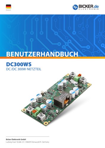 DC300WS
20 Pages
 UPSI-2406R2DP2MB
45 Pages
 UPSI-2406R2DP3MB
45 Pages
 UPSI-2412DP3
31 Pages
 UPSI-2412DP2
31 Pages
 UPSI-2406R2IP-38AC+PSZ-1100
31 Pages
 UPSI-2406R2IP-38AC
31 Pages
 UPSI-2406DP1
38 Pages
 UPSI-2406DP2
38 Pages
 UPS-1000-B1
32 Pages
 BE-DCEB5A
2 Pages
 BE-DCEB10A
2 Pages
 BP-LFP-13250S
18 Pages
 BP-LFP-10250S
18 Pages
 BP-LFP-1325S
19 Pages
 BP-LFP-1025S
19 Pages
 DC2412-UPSP2
9 Pages
 UPSI-2406IP-38AC
31 Pages
 BP-LFP-2725D
22 Pages
 BP-LFP-2725
22 Pages
 BP-LFP-1375D
5 Pages
 BP-LFP-1375
5 Pages
 BDCD-50xxC/T series
4 Pages
 UPSI-2412D
31 Pages
 UPSI-2406
3 Pages
 UPSI-2412
31 Pages
 BDCD-30CT SERIES
4 Pages
 BDC-30CT SERIES
4 Pages
 BDCD-10CT SERIES
4 Pages
 BDC-10CT SERIES
4 Pages
 BDCD-30VC SERIES
4 Pages
 BDC-30VC SERIES
4 Pages
 BDCD-10VC SERIES
4 Pages
 DC161W
5 Pages
 BEO-1400M SERIES
5 Pages
 BEP-520C
4 Pages
 BEO-3000MC SERIES
4 Pages
 BEO-2000MC SERIES
4 Pages
 BET-1600M SERIES
3 Pages
 BET-1500 SERIES
3 Pages
 BET-1000M SERIES
3 Pages
 BET-0900-T SERIES
6 Pages
 BET-0600M SERIES
3 Pages
 BET-0600 SERIES
3 Pages
 UPSI-2406IP-26UW
9 Pages
 UPSI-1208IP-11U
4 Pages
 IUPS-401
3 Pages
 DC2412-UPS
6 Pages
 UPSIC-1205
5 Pages
 UPSI-1208DP2
27 Pages
 UPSI-2406D
3 Pages
 UPSI-1208
3 Pages
 BES-540T
2 Pages
 BES-540C
2 Pages
 BEH-542C
3 Pages
 BEA-750H
4 Pages
 BEA-550K
4 Pages
 BEA-630
2 Pages
 BEP-530H
3 Pages
 BEP-520H
3 Pages
 BEP-510
3 Pages
 BDC-10VC SERIES
4 Pages
 DC160WS
5 Pages
 BEO-0800 SERIES
4 Pages
 DC160W
4 Pages
 DC1224
2 Pages
- DC power supply
- AC/DC power supply
- CE power supply
- Single-output power supply
- Switching power supply
- Power supply for industrial applications
- DC-DC converter
- Power supply with overload protection
- Compact power supply
- Tabletop power supply
- Rack-mount power supply
- Single-phase power supply
- DC/DC power supply
- Multiple-output power supply
- Telecommunications equipment power supply
- Laboratory power supply
- TUV power supply
- Industrial UPS
- Industrial DC/DC converter module