
- Catalogs
- Bicker Elektronik GmbH
- UPSI-2412DP2

UPSI-2412DP2

UPSI-2412DP2
The document introduces the UPSI-2412DP2 and UPSI-2412DP3, which are high-performance DC/DC UPS systems. The UPSI-2412DP2 uses Supercaps, while the UPSI-2412DP3 uses a LiFePO4 battery. These systems are designed to handle power outages and fluctuations, requiring a 24 V DC power supply and maintaining a regulated output voltage of 23.5 V DC during voltage drops.
Specifications
- Input Voltage: 24 V DC (22.8…30 V)
- Input Current: 11 A max.
- Output Voltage: Network operation: VIN– 0.6 V DC max.; Battery operation: 23.5 V DC
- Output Current: 10 A / 10.3…12 A for max. 10 s
- Capacitive Load: 10,000 µF
- Protection: Overcurrent and short circuit protection
- Interfaces: USB, RS232, HID-UPS
- Battery Technology: DP2: EDLC 13.5 kJ; DP3: LiFePO4 2.5 Ah
- Operating Temperature: DP2: -20…+70 °C; DP3: -20…+55 °C
- Dimensions: 111 x 157 x 131 mm
- Weight: 1.72 kg (DP2), 1.53 kg (DP3)
Safety Instructions
Users are warned to ensure proper wiring, avoid exposure to fire or extreme temperatures, and not operate in wet conditions. The device should not be opened or modified, and damaged units should not be used.
Usage and Software
The UPS is intended for use in protective enclosures and is suitable for industrial applications. The UPS Gen2 Configuration Software allows parameter settings and firmware updates, compatible with Microsoft® Windows.
Technical Data
- Input Voltage Range: 22.8 V DC…30 V DC
- Max Voltage: 35 V DC
- Power Consumption: 242 W (nominal), 264 W (max)
- Output Voltage (Battery Mode): 23.5 V DC
- Output Current: 10 A nominal, up to 12 A for short durations
Backup Time
The backup time varies based on battery capacity, load, and temperature, with graphical data provided for different models.
Technical Specifications
The UPSI-2412DPx series provides output power ranging from 235W to 282W, with short-circuit and no-load protection. Overcurrent shutdown occurs at 10.3-16.3A, with a maximum of 16.3A for 5ms. The device supports a battery start current of 7A and switches from mains to battery operation in less than 600µs.
Connection Details
The device uses screw connectors with a wire cross-section of 0.205-3.31mm². The torque for connections is between 0.5Nm and 0.6Nm. The UPSI-2412DP2 and UPSI-2412DP3 models have different energy storage specifications, with the former using EDLC technology and the latter using LiFePO4.
Relay and Interface
The relay connection is configurable via software, supporting power fail alarms with a switching voltage of 24V DC or 125V AC. The USB interface is USB 2.0 with a Type B connector, and the RS232 interface uses a DSUB 9-Pin connector.
General Data
The device is housed in an IP20-rated aluminum case, suitable for DIN rail mounting. It operates within a temperature range of -20°C to +70°C for DP2 and -20°C to +55°C for DP3, with a maximum humidity of 95% at 25°C.
Standards and Compliance
The device complies with IEC 61010-1 and EN 61000 standards for industrial environments, including static electricity discharge and electromagnetic field resistance.
Installation and Operation
Installation should be performed by qualified personnel, ensuring correct polarity and secure connections. The device supports vertical mounting for optimal convection and requires specific spacing from adjacent components.
Startup and Shutdown
The UPS can be started by connecting the supply voltage or via battery start for the UPSI-2412DP3 model. The device includes a shutdown diagram for managing power fail scenarios.
LED Status Indicators
The device features LED indicators for various statuses, including network operation, battery operation, and error states, with specific blink patterns for each condition.
Catalog excerpts

USV-SYSTEM DIN-RAIL Bicker Elektronik GmbH Ludwig-Auer-Straße 23 | 86609 Donauwörth · Germany
Open the catalog to page 1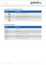
Achtung! Wichtiger Gefahrenhinweis. Nicht mit dem Hausmull entsorgen. Warnung vor elektrischer Spannung.
Open the catalog to page 2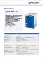
UPSI-2412DP2 / -DP3 24 V DC / 10 A © Leistungsstarke 24 V DC USV (DIN-Rail-Version) © Integrierte wartungsfreie Supercaps (DP2) ODER LiFePO4-Batterie (DP3) © Bis zu 500 000 Zyklen(DP2) | bis zu 5 000 Zyklen (DP3) © Kapazitat DP2: 13.5 kJ | DP3: 64 Wh © Intelligente Eingangsstromerkennung © Geregelte Ausgangsspannung im Batterie-Betrieb © Mindestlasterkennung © Power-fail Timer-Funktion © Relaiskontakt fur Power-fail © Reboot-Funktion © Ladezustandsanzeige © Herunterfahren durch externes Signal © UPSI-2412DP3 mit zusatzlicher Batteriestart-Funktion Technische Daten Ausgangsspannung Netzbetrieb:...
Open the catalog to page 4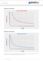
*Die Backup time ist abhangig von Batteriekapazitat, Last und Temperatur. Bei sehr hohen oder niedrigen Temperaturen verkurzt sich die Backup time. Sofern nicht anders angegeben, gelten die Werte fur Messungen bei +25°C.
Open the catalog to page 5
B Einführung und Beschreibung Vor Inbetriebnahme lesen! Dieses Handbuch soll den Anwender mit dem Produkt samt dessen Komponenten und Eigenschaften vertraut machen und möglichst vollständige und genaue Informationen dazu liefern. Das Handbuch sowie sämtliche Dokumente sind vor Installation und Benutzung genauestens zu lesen und einzuhalten. Ist dies nicht der Fall, können in bestimmten Situationen Garantie und Gewährleistung teilweise oder ganz entfallen. Für mögliche vorhandene Fehler sowie Nichteinhaltung der Gebrauchs- und Installationsvorgaben wird jegliche Haftung seitens Bicker Elektronik...
Open the catalog to page 7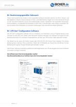
B2 BestimmungsgemaBer Gebrauch Dieses Gerat wurde fur den Einsatz in einem passenden Gehause entwickelt, welches vor Strom-, Wasser- und Brandgefahren schutzt, so dass ein Einsatz im Innen- und AuBenbereich moglich ist. Es ist primar fur den Einsatz auf der Hutschiene bestimmt und fur den professionellen Einsatz in Bereichen wie industrieller Steuerungs-, Kommunikations- und Messtechnik entwickelt. Es darf nicht in Vorrichtungen oder Anlagen verwendet wer-den, bei denen eine Fehlfunktion zu schweren Verletzungen fuhrt oder Menschenleben gefahrdet. Die UPS Gen2 Configuration Software wird zur...
Open the catalog to page 8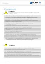
Missachtung nachfolgender Punkte kann einen elektrischen Schlag, Brände, schwere Unfälle oder Tod zur Folge haben. 1. Auf eine ordnungsgemäße und fachgerechte Verdrahtung muss geachtet werden. 2. Das Gerät darf weder Feuer noch Temperaturen außerhalb der Spezifikation ausgesetzt werden. 3. Das Gerät darf nicht unter Wasser getaucht und Spritzwasser ausgesetzt werden. 4. Das Gerät darf nicht in feuchter Umgebung oder in einer Umgebung, bei der mit Betauung oder Kondensation zu rechnen ist, betrieben werden. 5. Das Gerät darf nicht geöffnet, kurzgeschlossen, verpolt, überhitzt oder anderweitig...
Open the catalog to page 9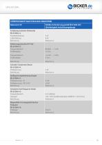
STORFESTIGKEIT NACH EN 61000 (INDUSTRIE) Erfullte Anforderung gemaft EN 61000 (CE) (Storfestigkeit Industrieumgebung) Entladung statischer Elektrizitat EN 61000-4-2
Open the catalog to page 16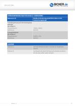
Basisnorm CE Erfullte Anforderung gemaG EN 61000-6-4 (CE) Bemerkung Konform Bemerkung Konform Kriterium A Normales Betriebsverhalten innerhalb der festgelegten Kriterium B Vorubergehende Beeintrachtigung des Betriebsverhaltens, die das Gerat selbst wieder korrigiert.
Open the catalog to page 17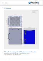
Sofern nicht anders angegeben, Toleranz nach: E Name / Adresse / Support E-Mail / Telefonnummer des Herstellers Bicker Elektronik GmbH • Ludwig-Auer-StraBe 23 • 86609 Donauworth • Germany E-Mail: [email protected] • Tel.: +49 (0) 906 70595-0
Open the catalog to page 18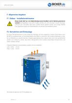
F Allgemeine Angaben F1 Einbau – Installationshinweise Dieses Gerät darf nur von Elektrofachpersonal installiert und in Betrieb genommen werden! Die Applikation muss beim Einbau stromlos sein. Die Leitungen müssen fest angeschlossen sein und dürfen über keine scharfen Kanten geführt werden. Auf richtige Polarität muss geachtet werden! Vor Inbetriebnahme Anschlüsse auf Korrektheit prüfen! F2 Konvektion und Einbaulage Für diese DIN-Rail-Versionen ist eine senkrechte Montage auf eine waagrechte Schiene (Hutschienen nach EN 60715) empfehlenswert, um die bestmögliche Konvektion zu erreichen. Eine...
Open the catalog to page 19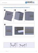
Hutschienenmontage und Hutschienenprofile nach EN 60715 Nach unten drücken
Open the catalog to page 20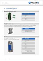
Die Funktion des Relais-Anschlusses kann per Software konfiguriert werden. Bei Schließen des Relais beträgt der Widerstand zwischen den beiden Pins ca. 0 Ω, ansonsten sind sie „open load“. RS-232 Zur Freigabe von PIN 8 muss PIN 1 dauerhaft nach PIN 5 (GND) geschaltet werden.
Open the catalog to page 21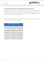
Es ist darauf zu achten, dass die vorgeschaltete Stromversorgung korrekt dimensioniert ist, um den Ladevorgang der Batterien und die korrekte Funktion der Applikation zu garantieren. Der Eingang muss von einer SELV- oder PELV-Stromversorgung gespeist werden. Um die USV-Gerate mit voller Funktionalitat zu betreiben, sol Ite die vorgeschaltete Stromversorgung mindestens 24 V / 20 A bereitstellen konnen und keine Konstantstrom-Funktion (constant current function) verwendet werden. Wird am Ausgang weniger Last als die Maximallast benotigt, kann die Spannungsversorgung nach der unten-stehenden Tabelle...
Open the catalog to page 22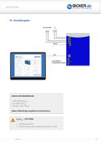
ANSCHLUSS-REIHENFOLGE 1. APPLIKATION (VOUT) Vin/Vout - achTung!
Open the catalog to page 23
F6 Inbetriebnahme Es muss sichergestellt sein, dass die USV ordnungsgemäß verbaut ist. Danach kann der Start auf zwei Wegen erfolgen: 1. Durch das Anschließen der Versorgungsspannung (standard): Wird an den Eingangsklemmen eine Spannung größer als 22.8 V angeschlossen, wird der Energiespeicher abgefragt und übermittelt seine Daten. Die USV stellt die entsprechende Ladeschlussspannung ein und gibt den Pack über das System Present frei. Danach beginnt der Ladevorgang des Energiespeichers. ODER 2. Batteriestart aus dem Energiespeicher in den Batterie-Betrieb (alternativ - nur mit USPI-2412DP3):...
Open the catalog to page 24All Bicker Elektronik GmbH catalogs and technical brochures
 DC300WS
20 Pages
 UPSI-2406R2DP2MB
45 Pages
 UPSI-2406R2DP3MB
45 Pages
 UPSI-2412DP3
31 Pages
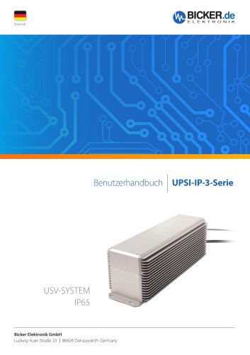 UPSI-2406R2IP-38AC+PSZ-1100
31 Pages
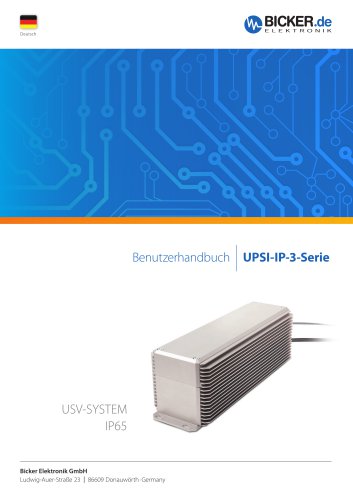 UPSI-2406R2IP-38AC
31 Pages
 UPSI-2406DP1
38 Pages
 UPSI-2406DP2
38 Pages
 UPS-1000-B1
32 Pages
 BE-DCEB5A
2 Pages
 BE-DCEB10A
2 Pages
 BP-LFP-13250S
18 Pages
 BP-LFP-10250S
18 Pages
 BP-LFP-1325S
19 Pages
 BP-LFP-1025S
19 Pages
 DC2412-UPSP2
9 Pages
 UPSI-2406IP-38AC
31 Pages
 BP-LFP-2725D
22 Pages
 BP-LFP-2725
22 Pages
 BP-LFP-1375D
5 Pages
 BP-LFP-1375
5 Pages
 BDCD-50xxC/T series
4 Pages
 UPSI-2412D
31 Pages
 UPSI-2406
3 Pages
 UPSI-2412
31 Pages
 BDCD-30CT SERIES
4 Pages
 BDC-30CT SERIES
4 Pages
 BDCD-10CT SERIES
4 Pages
 BDC-10CT SERIES
4 Pages
 BDCD-30VC SERIES
4 Pages
 BDC-30VC SERIES
4 Pages
 BDCD-10VC SERIES
4 Pages
 DC161W
5 Pages
 BEO-1400M SERIES
5 Pages
 BEP-520C
4 Pages
 BEO-3000MC SERIES
4 Pages
 BEO-2000MC SERIES
4 Pages
 BET-1600M SERIES
3 Pages
 BET-1500 SERIES
3 Pages
 BET-1000M SERIES
3 Pages
 BET-0900-T SERIES
6 Pages
 BET-0600M SERIES
3 Pages
 BET-0600 SERIES
3 Pages
 UPSI-2406IP-26UW
9 Pages
 UPSI-1208IP-11U
4 Pages
 IUPS-401
3 Pages
 DC2412-UPS
6 Pages
 UPSIC-2403
5 Pages
 UPSIC-1205
5 Pages
 UPSI-1208DP2
27 Pages
 UPSI-2406D
3 Pages
 UPSI-1208
3 Pages
 BES-540T
2 Pages
 BES-540C
2 Pages
 BEH-542C
3 Pages
 BEA-750H
4 Pages
 BEA-550K
4 Pages
 BEA-630
2 Pages
 BEP-530H
3 Pages
 BEP-520H
3 Pages
 BEP-510
3 Pages
 BDC-10VC SERIES
4 Pages
 DC160WS
5 Pages
 BEO-0800 SERIES
4 Pages
 DC160W
4 Pages
 DC1224
2 Pages
- Bicker DC power supply
- Bicker AC/DC power supply
- CE power supply
- Bicker single-output power supply
- Bicker power supply for industrial applications
- Bicker switching power supply
- DC-DC converter
- Compact power supply
- Tabletop power supply
- Power supply with overload protection
- Laboratory power supply
- Single-phase power supply
- Rack-mount power supply
- Bicker multiple-output power supply
- Electronic equipment power supply
- Bicker DC/DC power supply
- Bicker industrial UPS
- AC buffered power supply
- Industrial DC/DC converter module