
- Catalogs
- Bicker Elektronik GmbH
- UPSI-2412

UPSI-2412

UPSI-2412
This manual provides essential information about the UPSI-2412 product, including its components and features. Users must read and follow the manual and related documents to maintain warranty validity.
The UPSI-2412 is a high-performance DC/DC UPS system designed to handle voltage outages or fluctuations. It operates with a 24 V DC power supply and supports energy storage devices from Bicker Elektronik. The system switches to battery operation during voltage drops, maintaining a 23.5 V DC output.
Designed for professional use in industrial control, communication, and measurement technology, the device should not be used in life-threatening applications. Compliance with standards and EMC guidelines is required for the end product.
Adhering to safety instructions is crucial to prevent electric shock, fire, or accidents. Proper wiring and installation are mandatory.
Input Data: Operates with 24 V DC input, ranging from 22.8 V to 30 V DC, with overcurrent and short-circuit protection.
Output Data: Provides 24 V DC output in network operation and 23.5 V DC in battery operation, with a maximum output current of 10 A.
Battery Charging Unit: Supports LiFePO4 and EDLC technologies with a 4.5 A maximum charging current.
Features screw-type connectors for input/output and USB interfaces for data communication, including a relay interface for power fail alarms.
Regular maintenance and adherence to operational guidelines are recommended to ensure a long lifespan.
The device uses VCOM and HID protocols with a transmission length ≤ 3 m and access time < 1 second. It operates within -6 V DC to +6 V DC and uses an NXP chipset.
Classified under UL 94 V0 for flammability, the device weighs 0.125 kg and is designed as an open frame for installation. It operates between -20°C to +70°C and can be used at altitudes up to 4000 m.
Complies with IEC 61010-1 and IEC 61010-2-201 standards and CE requirements for industrial environments.
Installation should be done by qualified personnel with proper ventilation and spacing. The device should be mounted vertically.
Details on pin functions for RS232, USB, battery power, and temperature sensors are provided, along with connection sequences.
Includes features for handling overcurrent, short circuits, and polarity reversal, with instructions for starting the device using battery power.
LED indicators provide status updates for battery detection, overvoltage, overcurrent, and temperature errors.
Includes ignition timer, power fail detection, and shutdown protocols based on SOC and backup time thresholds.
Optimal charging voltage and operating temperature are crucial for battery longevity. Avoid heat sources and ensure good air circulation.
No maintenance is required. In case of failure, disconnect power, remove the battery, and clean with a dry cloth.
Follow local regulations for recycling and disposing of electronic devices and batteries.
Bicker Elektronik GmbH ensures compliance but cannot guarantee complete accuracy. Feedback is welcome.
Consider voltage drop in supply lines and avoid short circuits to prevent damage.
Catalog excerpts

USV-SYSTEM OPEN FRAME Bicker Elektronik GmbH Ludwig-Auer-Straße 23 | 86609 Donauwörth · Ger
Open the catalog to page 1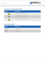
Legende der verwendeten Symbole Symbol Beschreibung Achtung! Wichtiger Gefahrenhinweis. Nicht mit dem Hausmüll entsorgen. Warnung vor elektrischer Spannung. Revisionsverzeichnis Datum
Open the catalog to page 2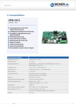
(Open Frame-Version) Intelligente Eingangsstromerkennung Geregelte Ausgangsspannung im Batterie-Betrieb Mindestlasterkennung Power-fail Timer-Funktion Relaiskontakt für Power-fail Reboot-Funktion Ladezustandsanzeige Batterie-Startfunktion Herunterfahren durch externes Signal Te ch n i s ch e Daten Eingangsspannung Eingangsstrom Ausgangsspannung Ausgangsstrom Kapazitive Last Ladeverfahren Schutzfunktionen Interface Mögliche Batterietechnologie Umgebungstemperatur Aufstellhöhe Max. zulässige Luftfeuchtigkeit Abmessungen B / H / T Gewicht 24 V DC (22.8…30 V) 11 A max. Netzbetrieb:...
Open the catalog to page 4
B Einführung und Beschreibung Vor Inbetriebnahme lesen! Dieses Handbuch soll den Anwender mit dem Produkt samt dessen Komponenten und Eigenschaften vertraut machen und möglichst vollständige und genaue Informationen dazu liefern. Das Handbuch sowie sämtliche Dokumente sind vor Installation und Benutzung genauestens zu lesen und einzuhalten. Ist dies nicht der Fall, können in bestimmten Situationen Garantie und Gewährleistung teilweise oder ganz entfallen. Für mögliche vorhandene Fehler sowie Nichteinhaltung der Gebrauchs- und Installationsvorgaben wird jegliche Haftung seitens Bicker Elektronik...
Open the catalog to page 6
B2 Bestimmungsgemäßer Gebrauch Dieses Gerät wurde für den Einsatz als Einbaugerät in einem Endprodukt mit Gehäuse und für den professionellen Einsatz in Bereichen wie industrieller Steuerungs-, Kommunikations- und Messtechnik entwickelt. Es darf nicht in Vorrichtungen oder Anlagen verwendet werden, bei denen eine Fehlfunktion zu schweren Verletzungen führt oder Menschenleben gefährdet. Der Inverkehrbringer oder Benutzer muss dafür sorgen, dass das Endprodukt die notwendigen Normen und EMV-Richtlinien einhält. Das Gehäuse des Endprodukts muss vor Strom-, Wasser- und Brandgefahr schützen, sodass...
Open the catalog to page 7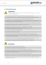
C Sicherheitshinweise WARNUNG! Missachtung nachfolgender Punkte kann einen elektrischen Schlag, Brände, schwere Unfälle oder Tod zur Folge haben. 1. Auf eine ordnungsgemäße und fachgerechte Verdrahtung muss geachtet werden. 2. Das Gerät darf weder Feuer noch Temperaturen außerhalb der Spezifikation ausgesetzt werden. 3. Das Gerät darf nicht unter Wasser getaucht und Spritzwasser ausgesetzt werden. 4. Das Gerät darf nicht in feuchter Umgebung oder in einer Umgebung, bei der mit Betauung oder Kondensation zu rechnen ist, betrieben werden. 5. Das Gerät darf nicht kurzgeschlossen, verpolt, überhitzt...
Open the catalog to page 8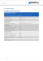
D Technische Daten D1 Allgemeine Technische Daten EINGANGSDATEN – UPSI-2412 Wenn nicht anders angegeben, gelten alle Angaben für 25° C Umgebungstemperatur, 24 V DC Eingangsspannung und Nennausgangstrom (IN ). Eingangsspannung Zuschaltschwelle fix Unterspannung Spannungsfall Eingang/Ausgang 21.6 V DC 0.6 V DC max. (abhängig von der Last) Stromaufnahme IN (UN, IOUT = IN, ICHARGE = 0) IMAX (UN, IOUT = ISTAT.BOOST, ICHARGE = max) IDYN (UN, IOUT = IDYN.BOOST, ICHARGE = 0) INO-LOAD (UN, IOUT = 0, ICHARGE = 0) ICHARGE (UN, IOUT = 0, ICHARGE = max) Leistungsaufnahme PN (UN, IOUT = IN, ICHARGE = 0) PMAX...
Open the catalog to page 9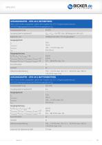
AUSGANGSDATEN – UPSI-2412 (NETZBETRIEB) Wenn nicht anders angegeben, gelten alle Angaben für 25° C Umgebungstemperatur, 24 V DC Eingangsspannung und Nennausgangstrom (IN ). Ausgangsspannung UOUT = UIN – 0.6 VDC max. (abhängig von der Last) Kapazitive Last Ausgangsstrom IN ISTAT.BOOST IDYN.BOOST ISFB Ausgangsleistung PN (UN, IOUT = IN, ICHARGE = 0) PSTAT.BOOST (UN, IOUT = ISTAT.BOOST, ICHARGE = 0) PDYN.BOOST (UN, IOUT = IDYN.BOOST, ICHARGE = 0) AUSGANGSDATEN – UPSI-2412 (BATTERIEBETRIEB) Wenn nicht anders angegeben, gelten alle Angaben für 25° C Umgebungstemperatur, 24 V DC Eingangsspannung und...
Open the catalog to page 10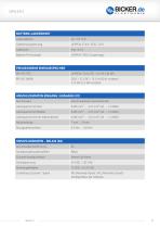
BATTERIE-LADEEINHEIT Ladeverfahren EDLC / 32 V DC / 13.5 kJ (9.0 kJ nutzbar) / 3.75 Wh (2.5 Wh nutzbar) ANSCHLUSSDATEN EINGANG / AUSGANG (X1) Anschlussart Verschraubbarer Steckverbinder Leiterquerschnitt starr Leiterquerschnitt flexibel ANSCHLUSSDATEN – RELAIS (X6) Anschlusskennzeichnung Schaltkontakt (potenzialfrei) Zustand (konfigurierbar) Power Fail Alarm Zuordnung Zustand - Signal NO (Normally Open) / NC (Normally Closed) – kon
Open the catalog to page 11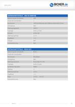
DATENSCHNITTSTELLE – USB (X3 ODER X8) Benennung der Schnittstelle USB-Typ B (Buchse) oder Stiftleiste, Rastermaß 2.54 mm DATENSCHNITTSTELLE – RS232 (X5) Benennung der Schnittstelle Symbolrate (Baudrate)
Open the catalog to page 12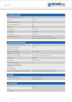
ALLGEMEINE DATEN Brennbarkeitsklasse nach UL 94 Open Frame 137 mm / 20 mm / 100 mm ±0.5 mm (inklusive Anschlüsse und höchsten Bauteilen) UMGEBUNGSBEDINGUNGEN Umgebungstemperatur (Betrieb) Umgebungstemperatur (Kaltstart unbelastet) Umgebungstemperatur (Lagerung / Transport) Nutzung im Innenbereich / Außenbereich Ja / Ja (Endprodukt muss zertifiziert werden) NORMEN Schutzkleinspannung
Open the catalog to page 13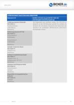
STÖRFESTIGKEIT NACH EN 61000 (INDUSTRIE) Basisnorm CE Erfüllte Anforderung gemäß EN 61000 (CE) (Störfestigkeit Industrieumgebung) Entladung statischer Elektrizität EN 61000-4-2 Kontaktentladung Luftentladung Bemerkung Das Endprodukt muss zertifiziert werden. Die UPSI-2412 ist designed, um alle Anforderungen gemäß CE zu erfüllen. Als Richtwert der erreichbaren Grenzwerte des Geräts kann das Handbuch der zertifizierten DIN-Rail-Version (UPSI-2412D) herangezogen werden. Elektromagnetisches HF-Feld EN 61000-4-3 Frequenzbereich Prüffeldstärke Frequenzbereich Prüffeldstärke Bemerkung Schnelle Transienten...
Open the catalog to page 14All Bicker Elektronik GmbH catalogs and technical brochures
 DC300WS
20 Pages
 UPSI-2406R2DP2MB
45 Pages
 UPSI-2406R2DP3MB
45 Pages
 UPSI-2412DP3
31 Pages
 UPSI-2412DP2
31 Pages
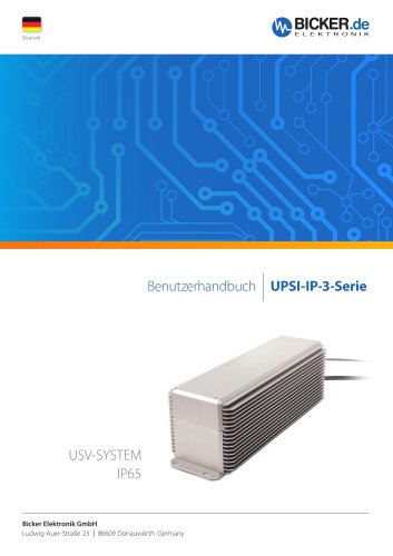 UPSI-2406R2IP-38AC+PSZ-1100
31 Pages
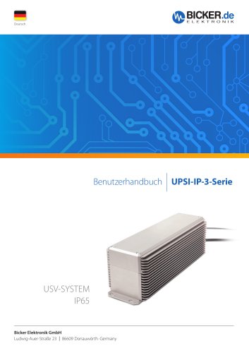 UPSI-2406R2IP-38AC
31 Pages
 UPSI-2406DP1
38 Pages
 UPSI-2406DP2
38 Pages
 UPS-1000-B1
32 Pages
 BE-DCEB5A
2 Pages
 BE-DCEB10A
2 Pages
 BP-LFP-13250S
18 Pages
 BP-LFP-10250S
18 Pages
 BP-LFP-1325S
19 Pages
 BP-LFP-1025S
19 Pages
 DC2412-UPSP2
9 Pages
 UPSI-2406IP-38AC
31 Pages
 BP-LFP-2725D
22 Pages
 BP-LFP-2725
22 Pages
 BP-LFP-1375D
5 Pages
 BP-LFP-1375
5 Pages
 BDCD-50xxC/T series
4 Pages
 UPSI-2412D
31 Pages
 UPSI-2406
3 Pages
 BDCD-30CT SERIES
4 Pages
 BDC-30CT SERIES
4 Pages
 BDCD-10CT SERIES
4 Pages
 BDC-10CT SERIES
4 Pages
 BDCD-30VC SERIES
4 Pages
 BDC-30VC SERIES
4 Pages
 BDCD-10VC SERIES
4 Pages
 DC161W
5 Pages
 BEO-1400M SERIES
5 Pages
 BEP-520C
4 Pages
 BEO-3000MC SERIES
4 Pages
 BEO-2000MC SERIES
4 Pages
 BET-1600M SERIES
3 Pages
 BET-1500 SERIES
3 Pages
 BET-1000M SERIES
3 Pages
 BET-0900-T SERIES
6 Pages
 BET-0600M SERIES
3 Pages
 BET-0600 SERIES
3 Pages
 UPSI-2406IP-26UW
9 Pages
 UPSI-1208IP-11U
4 Pages
 IUPS-401
3 Pages
 DC2412-UPS
6 Pages
 UPSIC-2403
5 Pages
 UPSIC-1205
5 Pages
 UPSI-1208DP2
27 Pages
 UPSI-2406D
3 Pages
 UPSI-1208
3 Pages
 BES-540T
2 Pages
 BES-540C
2 Pages
 BEH-542C
3 Pages
 BEA-750H
4 Pages
 BEA-550K
4 Pages
 BEA-630
2 Pages
 BEP-530H
3 Pages
 BEP-520H
3 Pages
 BEP-510
3 Pages
 BDC-10VC SERIES
4 Pages
 DC160WS
5 Pages
 BEO-0800 SERIES
4 Pages
 DC160W
4 Pages
 DC1224
2 Pages
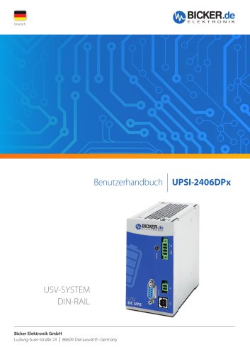
- Bicker DC power supply
- Bicker AC/DC power supply
- CE power supply
- Bicker single-output power supply
- Bicker power supply for industrial applications
- Bicker switching power supply
- DC-DC converter
- Compact power supply
- Tabletop power supply
- Power supply with overload protection
- Laboratory power supply
- Single-phase power supply
- Rack-mount power supply
- Bicker multiple-output power supply
- Electronic equipment power supply
- Bicker DC/DC power supply
- AC buffered power supply
- Bicker industrial UPS
- Industrial DC/DC converter module