- Catalogs
- Bicker Elektronik GmbH
- UPSI-1208DP2
- Company
- Products
- Catalogs
- News & Trends
- Exhibitions
UPSI-1208DP2
1 /27Pages

UPSI-1208DP2
1 /27Pages
Catalog excerpts

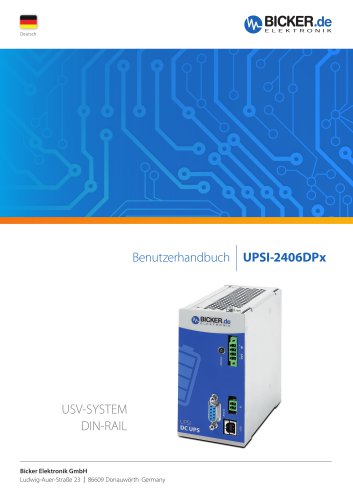
UPSI SYSTEM DIN-RAIL Bicker Elektronik GmbH Ludwig-Auer-Straße 23 | 86609 Donauwörth · Ger
Open the catalog to page 1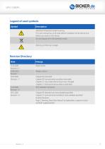
Legend of used symbols Symbol Description Revision Directory Change Date
Open the catalog to page 2
12 V DC / 8 A © 12 V DC UPS (DIN rail version) © Integrated maintenance-free Supercaps © Cycle Life >500 000 © Intelligent power sharing © Regulated output voltage in backup mode © Minimum load detection © Power fail Timer-Funktion © Relay dry contact on power fail ©USB & RS232 Interface © HID control center © Reboot-Funktion © Fuel gauge Technical Data Input voltage Input current Output voltage Output current Capacitive Load Charging method Protection Interface Type of battery Ambient temperature Operation altitude Humidity Dimensions W/ H / D Weight 12 VDC (11.5...16 V) 9.1 A max. Normal mode:...
Open the catalog to page 4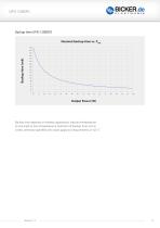
Backup time UPSI-1208DP2 Nominal backup time vs. Pout 320 300 280 Backup time depends on battery capacitance, load and temperature. At very high or low temperatures a reduction of backup time occurs. Unless otherwise specified, the values apply to measurements at +25 °C
Open the catalog to page 5
General Data
Open the catalog to page 6
B Intended use Congratulations for choosing a quality product! This manual shall help the user to get familiar with the product and its components and features. It shall provide information as accurately and completely as possible. However, for possible errors no liability can be assumed. Hints to existing mistakes, critics and suggestions for improvement are welcome at any time. B1 Description of the product and its functions UPSI-1208DP2 The UPSI-1208DP2 (hereinafter called UPS) is a DC/DC UPS system with numerous digital features and high performance. The UPS combines the UPSI-1208 with...
Open the catalog to page 7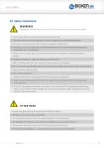
WARNING! Disregarding of following issues can result in electric shock, fire, serious injury or death. 1. Care must be taken to ensure proper and professional wiring. 2. The device pack must not be exposed to fire and temperatures outside the specification. 3. The device must not be immersed in water or exposed to splash water. 4. The device must not be operated in a humid environment or in an environment where dew and condensation are to be expected. 5. The device must not be opened, short-circuited, reversed, overheated or otherwise soldered / welded. 6. Changes or attempts to repair the device...
Open the catalog to page 8
CONNECTION DATA INPUT / OUTPUT Connection method Screw connection Conductor cross-section solid Conductor cross-section flexible Conductor cross-section with ferrule Stripping length Tightening torque ENERGY STORAGE UPSI-1208DP2 (BP-SUC-0835) Charging characteristic End-of-charge voltage Charging current Deep discharge protection Battery technology Nominal capacity Charging time
Open the catalog to page 11
INTERFERENCE IMMUNITY ACCORDING TO 61000-6-2 (INDUSTRY SECTOR) Basic standard CEl Normative minimum requirements EN 61000-6-2 (CE) (Interference immunity of industrial environment) Electrostatic discharge EN 61000-4-2 Housing contact discharge 4 kV (test level 2) Housing air discharge 8 kV (test level 3) Frequency range Test field strength Frequency range Test field strength Frequency range Test field strength Comment 80 MHz ... 1 GHz 10 V/m (test level 3) 1.4 GHz ... 2 GHz 3 V/m (test level 2) 2 GHz ... 2.7 GHz 1 V/m (test level 1) Criterion A INTERFERENCE IMMUNITY ACCORDING TO EN 61000-6-2...
Open the catalog to page 15
D Name / Address / Support E-Mail / Phone number of the manufacturer Bicker Elektronik GmbH • Ludwig-Auer-StraBe 23 • 86609 Donauworth • Germany E-Mail: [email protected] • Tel.: +49 (0) 906 70595-0
Open the catalog to page 16
E General Data E1 Assembly and installation advice Installation and operation of this device is only allowed to be executed from qualified personnel! The application must be separated from any power during the mounting process. Wires have to be connected safely and must not have contact with sharp edges. Pay attention to correct polarity! Before commissioning, check all the connections for correctness! E2 Convection and installation position Do not cover any ventilation holes by adjacent components. For this DIN rail versions, vertical mounting on a horizontal rail (DIN rails according to...
Open the catalog to page 17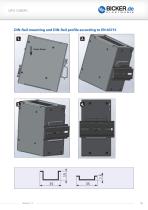
DIN-Rail mounting and DIN-Rail profile according to EN 60715
Open the catalog to page 18
RELAY CONNECTION (RL) Normally open contact (NO): When input power is interrupted, the contact is closed (= OQ).
Open the catalog to page 19
E4 Dimensioning the upstream power supply Ensure that the upstream power supply is correctly dimensioned to guarantee the charging process of the batteries and the correct functioning of the application. The input must be supplied from a SELV or PELV power supply. In order to operate the UPSI devices to the maximum, the upstream power supply has to provide at least the following output currents and voltages. If less load than the maximum load is required at the output of the UPSI devices, the voltage supply can be dimensioned according to the table below (column 3).
Open the catalog to page 20
E5 Initial operation Ensure that the UPS is correctly installed. Via connection to upstream power supply: When an input voltage higher than 11.5 V (UPSI-1208 DP2) is connected to the input terminals, the energy storage medium gets queried and transmits its data. Only then the charger gets enabled and the charging of the battery pack starts. This process lasts only a few milliseconds. The applied voltage at the input of the UPS is passed through to the output, reduced by a current-dependent voltage drop (Vout = Vin - 0.5 V at maximum current). The device charges the energy storage and monitors...
Open the catalog to page 21
CONNECTING ORDER 1. APPLICATION (VOUT) 2. DC SOURCE (VIN) 3. RELAY / USB / RS232 Dismantling order reverse to connection! VIN/VOUT – ATTENTION! 1. Note polarity! 2. AWG18 wire should be used (1 mm2)
Open the catalog to page 22
Charging times depend on storage medium, input voltage and the load current. E9 Reverse polarity / Overload / Short circuit The device is protected against reverse polarity at initial operation (device off, not active). When the device is operating in backup mode, reverse polarity protection not exists. If the load current is too high for a duration longer than 3 s, the device switches off (LED flashes quickly) and continues operation automatically after 10 s (non-latch). In the event of a short-circuit, the output is immediately disconnected. A start attempt is made every second (non-latch,...
Open the catalog to page 23All Bicker Elektronik GmbH catalogs and technical brochures
 DC300WS
20 Pages
 UPSI-2406R2DP2MB
45 Pages
 UPSI-2406R2DP3MB
45 Pages
 UPSI-2412DP3
31 Pages
 UPSI-2412DP2
31 Pages
 UPSI-2406R2IP-38AC+PSZ-1100
31 Pages
 UPSI-2406R2IP-38AC
31 Pages
 UPSI-2406DP1
38 Pages
 UPSI-2406DP2
38 Pages
 UPS-1000-B1
32 Pages
 BE-DCEB5A
2 Pages
 BE-DCEB10A
2 Pages
 BP-LFP-13250S
18 Pages
 BP-LFP-10250S
18 Pages
 BP-LFP-1325S
19 Pages
 BP-LFP-1025S
19 Pages
 DC2412-UPSP2
9 Pages
 UPSI-2406IP-38AC
31 Pages
 BP-LFP-2725D
22 Pages
 BP-LFP-2725
22 Pages
 BP-LFP-1375D
5 Pages
 BP-LFP-1375
5 Pages
 BDCD-50xxC/T series
4 Pages
 UPSI-2412D
31 Pages
 UPSI-2406
3 Pages
 UPSI-2412
31 Pages
 BDCD-30CT SERIES
4 Pages
 BDC-30CT SERIES
4 Pages
 BDCD-10CT SERIES
4 Pages
 BDC-10CT SERIES
4 Pages
 BDCD-30VC SERIES
4 Pages
 BDC-30VC SERIES
4 Pages
 BDCD-10VC SERIES
4 Pages
 DC161W
5 Pages
 BEO-1400M SERIES
5 Pages
 BEP-520C
4 Pages
 BEO-3000MC SERIES
4 Pages
 BEO-2000MC SERIES
4 Pages
 BET-1600M SERIES
3 Pages
 BET-1500 SERIES
3 Pages
 BET-1000M SERIES
3 Pages
 BET-0900-T SERIES
6 Pages
 BET-0600M SERIES
3 Pages
 BET-0600 SERIES
3 Pages
 UPSI-2406IP-26UW
9 Pages
 UPSI-1208IP-11U
4 Pages
 IUPS-401
3 Pages
 DC2412-UPS
6 Pages
 UPSIC-2403
5 Pages
 UPSIC-1205
5 Pages
 UPSI-2406D
3 Pages
 UPSI-1208
3 Pages
 BES-540T
2 Pages
 BES-540C
2 Pages
 BEH-542C
3 Pages
 BEA-750H
4 Pages
 BEA-550K
4 Pages
 BEA-630
2 Pages
 BEP-530H
3 Pages
 BEP-520H
3 Pages
 BEP-510
3 Pages
 BDC-10VC SERIES
4 Pages
 DC160WS
5 Pages
 BEO-0800 SERIES
4 Pages
 DC160W
4 Pages
 DC1224
2 Pages
- DC power supply
- AC/DC power supply
- CE power supply
- Single-output power supply
- Switching power supply
- Power supply for industrial applications
- DC-DC converter
- Power supply with overload protection
- Compact power supply
- Tabletop power supply
- Rack-mount power supply
- Single-phase power supply
- DC/DC power supply
- Multiple-output power supply
- Telecommunications equipment power supply
- Laboratory power supply
- TUV power supply
- Industrial UPS
- Industrial DC/DC converter module