
- Catalogs
- Bicker Elektronik GmbH
- UPS-1000-B1

UPS-1000-B1

UPS-1000-B1
The UPS-1000-B1 is a line-interactive uninterruptible power supply (UPS) with a sinusoidal output voltage, supporting a maximum power of 600 W / 1000 VA. It includes AVR (Automatic Voltage Regulation) with buck and boost functions, microprocessor control, and a battery backup time display. The device operates at approximately 97% efficiency and supports ambient temperatures up to +60°C. It features RS232 and USB interfaces for communication with UPSilon 2000 software and uses Hawker/Cyclon batteries.
The UPS accepts an input voltage of 230 V AC with a frequency range of 47 Hz to 65 Hz, providing output power at 230 V AC with a sinusoidal waveform and a crest factor of 3:1. The transfer time for blackout is typically 3 ms, and it includes overload protection with alarms and shutdown levels.
The UPS uses a BP-2480 battery pack with a voltage of 24 V DC, offering a typical backup time of 14 minutes at half load and 4.5 minutes at full load. The charging method includes smart pulse charging with fast and maintenance modes, taking approximately 5 hours to reach 90% capacity.
The device features RS232 and USB interfaces compatible with UPSilon2000, an LCD display, and acoustic alarms for low battery and improper operation. It includes fan control and an EBT system for backup time estimation.
The UPS operates within a temperature range of 0 to +60°C and a humidity range of 5 to 95% non-condensing. It complies with safety standard EN62040-1 and EMC standard EN62040-2.
The UPS measures 18 x 22 x 46 cm and weighs 15 kg. It is packaged individually, with 16-30 units per pallet.
The manual provides comprehensive information about the UPS-1000-B1, emphasizing the importance of reading all documents before installation and use to avoid voiding warranties. The UPS is designed to bridge power outages and fluctuations, automatically switching to battery operation when necessary.
The UPS is intended for use with a 230 V network and should be installed upright, away from liquids and excessive moisture. It is not suitable for medical or life-support systems and should not be used as an inverter.
Users must ensure proper wiring and avoid exposing the device to fire or extreme temperatures. The UPS should not be opened, short-circuited, or modified, and damaged units should not be used. Proper ventilation must be maintained.
Bicker Elektronik GmbH, Ludwig-Auer-Straße 23, 86609 Donauwörth, Germany. Support email: [email protected], Phone: +49 (0) 906 70595-0.
This device must be installed and commissioned by qualified electrical personnel only. Ensure the application is de-energized during installation. Cables must be securely connected and not routed over sharp edges. Verify connections before commissioning. Check the shipping carton for transport damage upon receipt and contact your carrier if issues arise. Always ship the UPS in its original packaging.
Connect the included power cable to the UPS and a 3-pole socket with PE. Connect the load (e.g., PC) to the UPS output. Use the included USB or RS232 cable to connect to a PC and install UPSilon2000 if necessary. The UPS-1000-B1 must be connected to a 16 A protected 3-pole circuit with PE. The total leakage current must not exceed 3.5 mA. The UPS can remain energized during a power outage.
The UPS-1000-B1 must be mounted upright. Do not exceed the maximum load, which can be found in the technical data section. Consider derating: 600 W load at +40°C, reducing by 10 W for each 1 K increase in temperature, allowing a maximum load of 400 W at +60°C. Ensure no foreign objects enter the UPS and the fan outlet remains unobstructed. Recommended clearances: Front: 50 mm, Back: 50 mm, Fan side (right): 50 mm.
The UPS offers two computer interfaces: RS-232 or USB for UPS management software UPSilon2000. Only one can be used at a time. RS-232 settings include a baud rate of 2400 bps, 8-bit data length, 1 stop bit, and no parity.
Turning On the UPS: The UPS is connected to the power grid, and the internal battery charges. The battery symbol blinks on the LCD display, showing the battery level. If the automatic start function is enabled, the UPS turns on and activates the output sockets. If disabled, press the Power ON/OFF button to turn on.
Turning Off the UPS: Press the Power ON/OFF button for 4 seconds to turn off the output sockets and the UPS after about 10 seconds. The display will show "OFF." The battery charges even when the UPS is off.
Cold Start: The UPS can be turned on without input power by pressing the Power ON/OFF button for 1 second. The display will show "OFF," then press the button again.
"OFF" Mode: In "OFF" mode, the UPS shuts down within 10 seconds during a power outage or when the power cord is unplugged.
Self-Test Button: For a battery load test, disconnect the power cord to simulate a power outage, or press the SELF Test button to internally disconnect power for 10 seconds. To cancel, press the SELF Test button for 2 seconds.
Alarm Reset: During a power outage, the buzzer beeps twice every 8 seconds. Press the Alarm Reset button to toggle the alarm. The speaker symbol appears on the LCD. The button is non-functional at 0 W load.
Weak Battery Alarm: A low battery voltage triggers multiple warnings, and the deep discharge protection shuts down the UPS.
Battery Charging: The UPS offers fast charging and trickle charging modes. Fast charging provides higher current when the battery is empty and reduces as voltage increases. Trickle charging starts automatically at 90% charge.
Settings can be changed via factory software or the LCD display. To change settings on the LCD, press both selection buttons simultaneously for 3 seconds until the display blinks. Navigate through the menu by pressing both buttons again.
Changing Output Frequency (Cold Start Only): When the frequency value blinks, press any selection button for 1 second to change the frequency. The setting changes every 2 seconds when the button is pressed. Press both buttons simultaneously to proceed to the next setting. The display stops blinking after 30 seconds without further input.
Changing Output Voltage (UPS Operation): When the output voltage value blinks, press any selection button for 1 second to change the voltage. The setting changes every 2 seconds when the button is pressed. Proceed to the next menu item by pressing both selection buttons simultaneously. The display stops blinking after 30 seconds without further input.
The LCD display and controls include: Power ON/OFF button, SELF TEST button, ALARM RESET button, and SELECT buttons for modes and settings.
Features include: 1. Fuse 6.3 AT, 2. Power input, 3. UPS output, 4. RS232 interface, 5. USB interface, 6. Data-line protection (RJ-45, optional), 7. External battery connection (not for UPS-1000-B1), 8. Internal SNMP slot (not for UPS-1000-B1), 9. Sidewall fan blowing outward.
The LCD display provides various indicators such as overload, load level, normal mode, battery mode, self-test, AVR modes, timer enabled, temperature alarm, fan operation, acoustic alarm status, UPS error, battery status, and battery replacement alerts.
Catalog excerpts

Bicker Elektronik GmbH Ludwig-Auer-Straße 23 | 86609 Donauwörth · Ger
Open the catalog to page 1
Beschreibung Achtung! Wichtiger Gefahrenhinweis. Nicht mit dem Hausmull entsorgen. Warnung vor elektrischer Spannung.
Open the catalog to page 2
UPS-1000-B1 600 W / 1000 VA © Line Interactive Design mit Sinus-Ausgangsspannung © AVR-Funktion (Buck/ Boost) © Mikroprozessorgestutzte Steuerung © Batterie-Backup Zeitanzeige © Umgebungstemperatur bis +60 °C © Reboot-Funktion © Lastsensor © RS232- und USB-Schnittstelle fur Kommuni-kation mit Software UPSilon 2000 © Hawker/Cyclon-Batterien
Open the catalog to page 4
AUSGANGSDATEN Ausgangsleistung bei Nennspannung 230 V AC 600 W / 1000 VA max. bei +40 °C Leistungsrücknahme Crest Faktor Ausgangsfrequenz (synchronisiert zum Netz) Auto select für 50/60 Hz 47 Hz ~ 55 Hz für 50 Hz nominal; 56 Hz ~ 65 Hz für 60 Hz nominal Transfer Zeit Blackout 3 ms typisch, Brownout 1 ms, Batteriebetrieb zu Netzbetrieb: 1 ms typisch Überlast-Alarm Level 100 % ~ 120 %, Überlast Shutdown Level 120 % ~ 190 % BATTERIE Batterietyp Typische Backup Zeit bei halber Leistung Typische Backup Zeit bei voller Leistung Smart Puls Ladung mit 2 Lademodi: Schnellladung, Erhaltungsladung, ab 90 %...
Open the catalog to page 5
B Einführung und Beschreibung Vor Inbetriebnahme lesen! Dieses Handbuch soll den Anwender mit dem Produkt samt dessen Komponenten und Eigenschaften vertraut machen und möglichst vollständige und genaue Informationen dazu liefern. Das Handbuch sowie sämtliche Dokumente sind vor Installation und Benutzung genauestens zu lesen und einzuhalten. Ist dies nicht der Fall, können in bestimmten Situationen Garantie und Gewährleistung teilweise oder ganz entfallen. Für mögliche vorhandene Fehler sowie Nichteinhaltung der Gebrauchs- und Installationsvorgaben wird jegliche Haftung seitens Bicker Elektronik...
Open the catalog to page 8
B2 Bestimmungsgemäßer Gebrauch • Die USV ist für das Netz 230 V ausgelegt. • Die UPS-1000-B1 darf nur stehend montiert werden. • Installieren Sie die USV niemals in der Nähe von Flüssigkeiten oder in einer übermäßig feuchten Umgebung. • Setzen Sie die USV niemals direktem Sonnenlicht oder einer Wärmequelle aus. • Nach der Erstinstallation an das Wechselstromnetz beginnt die Ladung des Akkus. • Die volle Aufladung benötigt ca. 8 Stunden. • Um Batterieschäden zu minimieren, ist die USV vor Einlagerung zu laden und alle 6 Monate nachzuladen. • Die USV darf nicht als Wechselrichter zweckentfremdet...
Open the catalog to page 9
C Sicherheitshinweise WARNUNG! Missachtung nachfolgender Punkte kann einen elektrischen Schlag, Brande, schwere Unfalle oder Tod zur Folge haben. 1. Auf eine ordnungsgemaBe und fachgerechte Verdrahtung muss geachtet werden. 2. Das Gerat darf weder Feuer noch Temperaturen auBerhalb der Spezifikation ausgesetzt werden. 3. Die USV ist fur das Netz 230 V ausgelegt. 4. Das Gerat darf nicht in feuchter Umgebung oder in einer Umgebung, bei der mit Betauung oder Kondensation zu rechnen ist, betrieben werden. 5. Das Gerat darf nicht geoffnet, kurzgeschlossen, verpolt, uberhitzt oder anderweitig modifiziert...
Open the catalog to page 10
ACHTUNG! 1. Durch unsachgemäßen Gebrauch sowie durch Öffnen des Gerätes erlischt die Garantie/Gewährleistung. 2. Das Gerät darf nur bestimmungsgemäß verwendet werden. 3. Die nationalen Unfallverhütungs- und Sicherheitsvorschriften sind einzuhalten. 4. Die Montage des Gerätes sowie die elektrische Installation müssen dem Stand der Technik entsprechen. 5. Die elektrischen, thermischen und mechanischen Grenzwerte sind einzuhalten. 6. Die Angaben zur Verdrahtung der USV – wie in diesem Handbuch beschrieben – müssen eingehalten werden. 7. Nach der Erstinstallation an das Wechselstromnetz beginnt die...
Open the catalog to page 11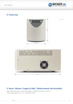
E Name / Adresse / Support E-Mail / Telefonnummer des Herstellers Bicker Elektronik GmbH · Ludwig-Auer-Straße 23 · 86609 Donauwörth · Germany E-Mail: [email protected] · Tel.: +49 (0) 906 70595-0
Open the catalog to page 12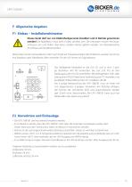
F Allgemeine Angaben F1 Einbau – Installationshinweise Dieses Gerät darf nur von Elektrofachpersonal installiert und in Betrieb genommen werden! Die Applikation muss beim Einbau stromlos sein. Die Leitungen müssen fest angeschlossen sein und dürfen über keine scharfen Kanten geführt werden. Vor Inbetriebnahme Anschlüsse auf Korrektheit prüfen! Bitte prüfen Sie den Versandkarton sofort nach Erhalt auf Transportschäden. Bei Problemen wenden Sie sich an Ihre Spedition oder Paketdienst. Bitte versenden Sie die USV immer im Originalkarton. Das beiliegende Netzkabel an die USV (2) und in eine 3 polige...
Open the catalog to page 13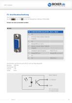
Die USV bietet zwei Computerschnittstellen: RS-232 oder USB Die Definition und Einrichtung fur RS232 wird wie folgt dargestellt: Baudrate: 2400 bps Paritat: Keine
Open the catalog to page 14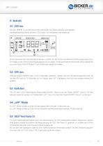
G Betrieb G1 USV ein Die UPS-1000-B1 ist mit dem Stromnetz verbunden. Die interne Batterie wird geladen. Das Batteriesymbol blinkt auf dem LCD Display. Der Akkupegel wird angezeigt. Ist die automatische Einschaltfunktion aktiviert, schaltet sich die USV ein und aktiviert die Netzausgangsbuchsen. 1 POWER ON/OFF Ein/Aus Taster Im Display ist die momentane Eingangsspannung zu sehen. Ist die automatische Einschaltfunktion deaktiviert SELF TEST Selbsttest ALARM RESET Alarm Knopf (1) zum Einschalten gedrückt werden. muss der Power ON/OFF aus 2 SELECT Auswahltasten für Modi und Einstellungen...
Open the catalog to page 16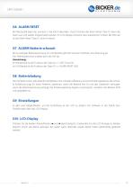
G6 ALARM RESET Bei Netzausfall piept der Summer 2 mal alle 8 Sekunden. Durch Drücken der Alarm Reset Taste (1) kann der Alarm aus und wieder eingeschaltet werden. Im LCD-Display erscheint das Lautsprecher Symbol. Bei 0 W Last ist der Alarm Reset Taste (1) ohne Funktion. G7 ALARM Batterie schwach Bei zu niedriger Batteriespannung (im USV Betrieb) gibt der Summer mehrfach eine Warnung ab. Der Tiefentladeschutz schaltet dann die USV ab. Anmerkung: Im Netzbetrieb ist die Funktion der Taste (1) >> SELF Test (G5) Im USV Betrieb ist die Funktion der Taste (1) >> ALARM RESET (G6) G8 Batterieladung...
Open the catalog to page 17All Bicker Elektronik GmbH catalogs and technical brochures
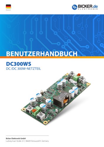 DC300WS
20 Pages
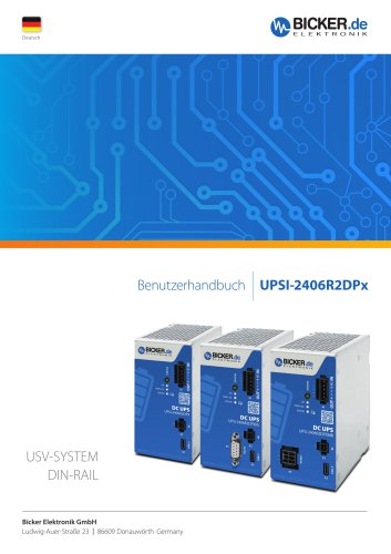 UPSI-2406R2DP2MB
45 Pages
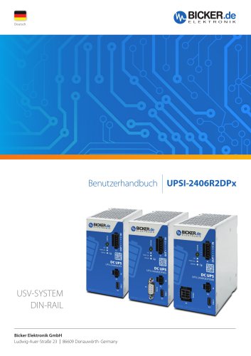 UPSI-2406R2DP3MB
45 Pages
 UPSI-2412DP3
31 Pages
 UPSI-2412DP2
31 Pages
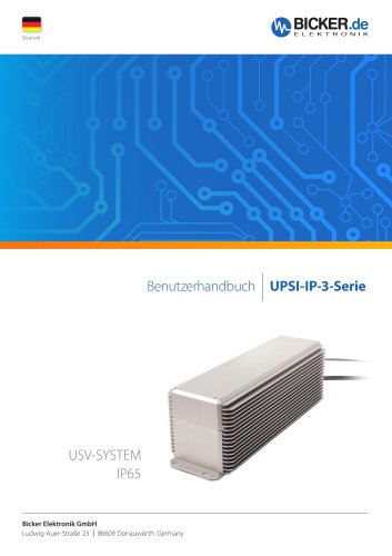 UPSI-2406R2IP-38AC+PSZ-1100
31 Pages
 UPSI-2406R2IP-38AC
31 Pages
 UPSI-2406DP1
38 Pages
 UPSI-2406DP2
38 Pages
 BE-DCEB5A
2 Pages
 BE-DCEB10A
2 Pages
 BP-LFP-13250S
18 Pages
 BP-LFP-10250S
18 Pages
 BP-LFP-1325S
19 Pages
 BP-LFP-1025S
19 Pages
 DC2412-UPSP2
9 Pages
 UPSI-2406IP-38AC
31 Pages
 BP-LFP-2725D
22 Pages
 BP-LFP-2725
22 Pages
 BP-LFP-1375D
5 Pages
 BP-LFP-1375
5 Pages
 BDCD-50xxC/T series
4 Pages
 UPSI-2412D
31 Pages
 UPSI-2406
3 Pages
 UPSI-2412
31 Pages
 BDCD-30CT SERIES
4 Pages
 BDC-30CT SERIES
4 Pages
 BDCD-10CT SERIES
4 Pages
 BDC-10CT SERIES
4 Pages
 BDCD-30VC SERIES
4 Pages
 BDC-30VC SERIES
4 Pages
 BDCD-10VC SERIES
4 Pages
 DC161W
5 Pages
 BEO-1400M SERIES
5 Pages
 BEP-520C
4 Pages
 BEO-3000MC SERIES
4 Pages
 BEO-2000MC SERIES
4 Pages
 BET-1600M SERIES
3 Pages
 BET-1500 SERIES
3 Pages
 BET-1000M SERIES
3 Pages
 BET-0900-T SERIES
6 Pages
 BET-0600M SERIES
3 Pages
 BET-0600 SERIES
3 Pages
 UPSI-2406IP-26UW
9 Pages
 UPSI-1208IP-11U
4 Pages
 IUPS-401
3 Pages
 DC2412-UPS
6 Pages
 UPSIC-2403
5 Pages
 UPSIC-1205
5 Pages
 UPSI-1208DP2
27 Pages
 UPSI-2406D
3 Pages
 UPSI-1208
3 Pages
 BES-540T
2 Pages
 BES-540C
2 Pages
 BEH-542C
3 Pages
 BEA-750H
4 Pages
 BEA-550K
4 Pages
 BEA-630
2 Pages
 BEP-530H
3 Pages
 BEP-520H
3 Pages
 BEP-510
3 Pages
 BDC-10VC SERIES
4 Pages
 DC160WS
5 Pages
 BEO-0800 SERIES
4 Pages
 DC160W
4 Pages
 DC1224
2 Pages
- Bicker DC power supply
- Bicker AC/DC power supply
- CE power supply
- Bicker single-output power supply
- Bicker power supply for industrial applications
- Bicker switching power supply
- DC-DC converter
- Compact power supply
- Tabletop power supply
- Power supply with overload protection
- Laboratory power supply
- Single-phase power supply
- Rack-mount power supply
- Bicker multiple-output power supply
- Electronic equipment power supply
- Bicker DC/DC power supply
- Bicker industrial UPS
- AC buffered power supply
- Industrial DC/DC converter module