
- Catalogs
- Bicker Elektronik GmbH
- BE-DCEB5A

BE-DCEB5A

BE-DCEB5A
- Input Voltage: 8 to 40 VDC
- Inrush Current Limitation: Approximately 13 A
- Maximum Load Current: 5 A
- Rise Time at Nominal Current: 10 to 50 ms, typically 13 ms at 24 V
- On Resistance: Maximum 50 mΩ, typically 20 mΩ at 24 A
- Dissipation Loss: Maximum 1 W at 5 A, typically 500 mW at 24 V / 5 A
- Connection: Screw terminals
- Dimensions: 48 x 26 x 13 mm
- The inrush current limiter is designed for use with capacitive loads.
- Inrush current is limited only during start-up.
- When integrating a switch, refer to the provided diagram for correct installation.
- The document includes a drawing with dimensions and tolerances for installation purposes.
- Key measurements include 48.0 mm length, 26.0 mm width, and 13.0 mm height.
Catalog excerpts

Zubehör / Accessories Accessories Inrush current limiter Input voltage: 8…40 V DC Inrush current limited to app. 13 A Max. load current: 5A For use with a capacitive load Technical data Input voltage Inrush current limited to Max. load current Rise time at nominal current On resistance Dissipation loss Connection Dimensions 8…40 VDC Approx. 13 A 5 A 10…50 ms max., typ. 13 ms at 24 V Max. 50 mΩ, typ. 20 mΩ at 24 A Max. 1 W at 5 A, typ. 500 mW at 24 V / 5 A Screw terminals 48 x 26 x 13 mm Note: Inrush current is just limited during start-up! Beispiel / Example WITH inrush current limiter WITHOUT inrush current limiter The measurement was conducted using a 4700 µF electrolytic capacitor at 4 A capacitive load. Bicker Elektronik GmbH | 86609 Donauwörth | Deutschland Tel.
Open the catalog to page 1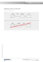
Zubehör / Accessories Application note for use with switch When a switch is needed, follow picture 1! Irrtümer und technische Änderungen vorbehalten! Stand: 20.07.2023 Bicker Elektronik GmbH | 86609 Donauwörth | Deutschland Tel. +49 906 70595-0 | [email protected] |
Open the catalog to page 2All Bicker Elektronik GmbH catalogs and technical brochures
 DC300WS
20 Pages
 UPSI-2406R2DP2MB
45 Pages
 UPSI-2406R2DP3MB
45 Pages
 UPSI-2412DP3
31 Pages
 UPSI-2412DP2
31 Pages
 UPSI-2406R2IP-38AC+PSZ-1100
31 Pages
 UPSI-2406R2IP-38AC
31 Pages
 UPSI-2406DP1
38 Pages
 UPSI-2406DP2
38 Pages
 UPS-1000-B1
32 Pages
 BE-DCEB10A
2 Pages
 BP-LFP-13250S
18 Pages
 BP-LFP-10250S
18 Pages
 BP-LFP-1325S
19 Pages
 BP-LFP-1025S
19 Pages
 DC2412-UPSP2
9 Pages
 UPSI-2406IP-38AC
31 Pages
 BP-LFP-2725D
22 Pages
 BP-LFP-2725
22 Pages
 BP-LFP-1375D
5 Pages
 BP-LFP-1375
5 Pages
 BDCD-50xxC/T series
4 Pages
 UPSI-2412D
31 Pages
 UPSI-2406
3 Pages
 UPSI-2412
31 Pages
 BDCD-30CT SERIES
4 Pages
 BDC-30CT SERIES
4 Pages
 BDCD-10CT SERIES
4 Pages
 BDC-10CT SERIES
4 Pages
 BDCD-30VC SERIES
4 Pages
 BDC-30VC SERIES
4 Pages
 BDCD-10VC SERIES
4 Pages
 DC161W
5 Pages
 BEO-1400M SERIES
5 Pages
 BEP-520C
4 Pages
 BEO-3000MC SERIES
4 Pages
 BEO-2000MC SERIES
4 Pages
 BET-1600M SERIES
3 Pages
 BET-1500 SERIES
3 Pages
 BET-1000M SERIES
3 Pages
 BET-0900-T SERIES
6 Pages
 BET-0600M SERIES
3 Pages
 BET-0600 SERIES
3 Pages
 UPSI-2406IP-26UW
9 Pages
 UPSI-1208IP-11U
4 Pages
 IUPS-401
3 Pages
 DC2412-UPS
6 Pages
 UPSIC-2403
5 Pages
 UPSIC-1205
5 Pages
 UPSI-1208DP2
27 Pages
 UPSI-2406D
3 Pages
 UPSI-1208
3 Pages
 BES-540T
2 Pages
 BES-540C
2 Pages
 BEH-542C
3 Pages
 BEA-750H
4 Pages
 BEA-550K
4 Pages
 BEA-630
2 Pages
 BEP-530H
3 Pages
 BEP-520H
3 Pages
 BEP-510
3 Pages
 BDC-10VC SERIES
4 Pages
 DC160WS
5 Pages
 BEO-0800 SERIES
4 Pages
 DC160W
4 Pages
 DC1224
2 Pages
- Bicker power supply
- Bicker DC power supply
- Bicker AC/DC power supply
- CE power supply
- Bicker single-output power supply
- Bicker power supply for industrial applications
- Bicker switching power supply
- DC-DC converter
- Compact power supply
- Tabletop power supply
- Power supply with overload protection
- Laboratory power supply
- Single-phase power supply
- Rack-mount power supply
- Bicker multiple-output power supply
- Electronic equipment power supply
- Bicker DC/DC power supply
- AC buffered power supply
- Bicker industrial UPS
- Industrial DC/DC converter module