Engineering Information
1 /9Pages

Engineering Information
1 /9Pages
Catalog excerpts

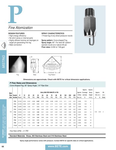
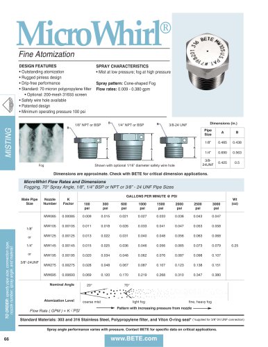
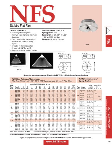
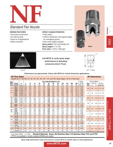
eering. Engineering. Engineering. Engineering. Engineeri Engineering Information SPECIFYING SPRAY NOZZLES Spray nozzles have three basic functions: • meter flow • distribute liquid • break up a liquid stream into droplets The process of choosing a nozzle includes specifying: a.) its flow‑rate‑versus‑pressure characteristics (see catalog flow rate tables) b.) how the droplets will be distri‑ buted after leaving the nozzle (see spray pattern, pp. 2, 3) c.) the size of the droplets that will be produced (contact BETE Applications Engineering if droplet size is critical) d.) the nozzle connection to the feed pipe (see dimension tables) e.) the material of construction (see page 12 for complete list) Calculate Total Water Flow and Pressure at Pump for Nozzles Operating at 0.5 bar Total Flow (p. 26, 27) = (1 nozzles)(381 l/min/nozzle) = 381 l/min Pump Pressure Formula: Ppump = Pnozzle + Ppipe losses + ρgh/100000 Calculate Pipe Loss: Pipe Friction: (15 m)(0.7 bar/100 m) = 0.11 bar Fitting Loss: (3 elbows)(1.52 m/elbow) = 4.56 m (4.56 m)(0.7 bar/100 m) = 0.03 bar Total Piping Losses: 0.11 bar + 0.03 bar = 0.14 bar Elevation Losses: (1000)(9.81)(12 m) / 100000 = 1.17 bar Ppump = 0.5 bar + 0.14 bar + 1.17 bar = 1.81 bar Pump must be sized to provide 381 l/min at 1.81 bar FLOW RATE The volume of liquid flowing through a nozzle depends primari‑ ly on the difference in fluid pres‑ sure upstream of its orifice and the pressure into which the nozzle dis‑ charges (normally that of the at‑ mosphere). Pressures that are list‑ ed in the flow rate tables of each nozzle series are gauge pressures. Flow rates for pressures not tab‑ ulated may be calculated using the equation given at the bottom of each table. The factor “K” is listed for each nozzle and has units of lpm/barx. A nozzle may discharge into a vessel where the pressure is not atmospheric. Since the nozzle flow rate is determined by the differen‑ tial pressure across it, the flow rate may be calculated by subtracting the gauge pressure inside the ves‑ sel from the gauge pressure at the nozzle inlet as shown: l/min = K (BarInlet - BarVessel ) x FLUID PROPERTIES (at room temperature) Specific Gravity FLUID PROPERTIES Specific gravity primarily affects nozzle flow. Flow rates of liquids denser than water are lower than flow rates of water at the same pressure because more energy is required to accelerate denser fluids. The following relationship exists between flow rates (Q)of fluids with different specific gravities: Viscosity also affects nozzle performance. High viscosities inhibit atomization. In general, fluids with viscosities greater than 100 cP are difficult to atomize
Open the catalog to page 1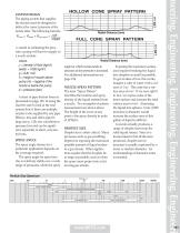
HOLLOW CONE SPRAY PATTERN Radial Distance (mm) FULL CONE SPRAY PATTERN SYSTEM DESIGN The piping system that supplies the nozzles must be designed to deliver the correct pressure at the nozzle inlet. The following formula p_ = p + p_ + pgh Pump Nozzle Pipe Losses 100000 is useful in estimating the pressure a pump will have to supply to a nozzle system: where: p = density of fluid (kg/m3) [water = 1000 kg/m3] g = 9.81 m/s2 h = height of nozzle above pump (m) - negative if the nozzle is below the pump p = pressure (bar) A chart of pipe friction losses is presented on page 125. In using...
Open the catalog to page 2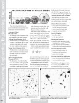
eering. Engineering. Engineering. Engineering. Engineeri RELATIVE DROP SIZE BY NOZZLE SERIES The following definitions are given for the most frequently used mean and median diameters: Arithmetic Mean Diameter (D10) • The average of the diameters of all the droplets in the spray sample. Volume Mean Diameter (D30) • The diameter of a droplet whose volume, if multiplied by the total number of droplets, will equal the total volume of the sample. Sauter Mean Diameter (D32): • The diameter of a droplet whose ratio of volume to surface area is equal to that of the complete spray sample. Mass (Volume)...
Open the catalog to page 3
RESEARCH & DEVELOPMENT BETE’s state‑of‑the‑art Spray Laboratory plays a key role in sup‑ porting both product R&D and our customer service network. Equipped with sophisticated video‑image processing and digi‑ tal analysis technology, the Spray Lab makes possible rapid nozzle development and evaluation. The Spray Lab is also available on a contract basis to provide con‑ fidential, quantitative evaluation of nozzle performance. Industrial applications for contract testing range from comparative nozzle performance testing to develop‑ ment of proprietary designs. These capabilities allow our customers...
Open the catalog to page 4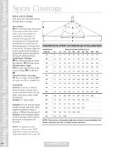
leering. Engineering. Engineering. Engineering. Engineeri THEORETICAL SPRAY COVERAGE (E) IN MILLIMETERS NOTE: Data shown is theoretical and does not take into consideration the effects of gravity, gas flow, or high pressure operation. Spray Coverage SPRAY ANGLE TERMS Four terms are commonly used to describe spray coverage: Spray Angle: (A) The included angle of the spray as measured close to the nozzle orifice. Since the droplets are immediately acted upon by external forces (gravity and moving gases, for example), this measurement is useful only for determining spray coverage close to the nozzle....
Open the catalog to page 5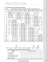
Valve & Fitting Losses Expressed in Equivalent Meters of PipePipe Fitting Nominal Pipe or Tube Size (mm)_or Valve_10 15 20 25 32 40 50 65 80 90 100 1 90* Standard Elbow 2 45* Standard Elbow 3 Flow-Through Branch Tee 4 Straight Through Flow Tee - No Reduction 5 Straight Through Flow Tee- Reduced 1/4 6 Straight Through Flow Tee - Reduced 1/8 7 Globe Valve - Fully opened 8 Gate Valve - Fully opened www.BETE.com neering. Engineering. Engineering. Engineering. Engineeri
Open the catalog to page 6
Notes! FLOW OF AIR THROUGH SCHEDULE 40 STEEL PIPE Pressure Drop per 100m of Schedule 40 Pipe For Air For 15°C and 7 bar gauge pressure 1/8" 0.093 0.337 0.719 1.278 1.942
Open the catalog to page 7
Nominal Pipe Size NPS [DN] Nominal Pipe Size NPS [DN]
Open the catalog to page 8
eering. Engineering. Engineering. Engineering. Engineeri 128 BETE Fog Nozzle, Inc. Application Information Sheet email: [email protected] Company Address: BETE Cust. # Sketch a simple representation of the application below: • What are you trying to accomplish with the spray? • What is the available pressure? • What is the desired material of construction? • What is the flow rate? • What is the piping material? • What is the desired flow rate? • What are the size and connection types desired? • What liquid is being sprayed? • What is the distance from the nozzle to the target? • What is the desired...
Open the catalog to page 9All BETE catalogs and technical brochures
 WL metric
1 Page
 PJ metric
1 Page
 NF
NF1 Page
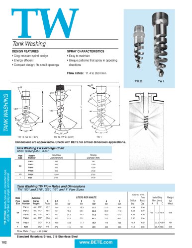 TW metric
1 Page
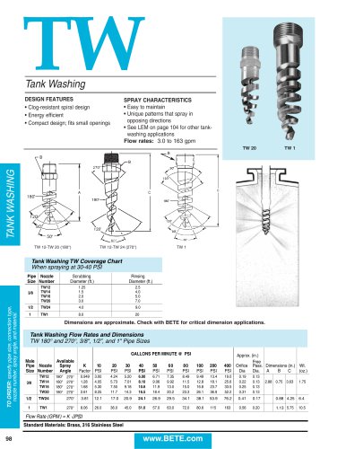 TW
TW1 Page
 AFF metric
1 Page
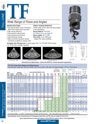
 TF10-170
1 Page
 TF24
TF241 Page
 TF FM Approved
1 Page
 TF metric
1 Page
 MaxiPass®
2 Pages
 HydroClaw®
2 Pages
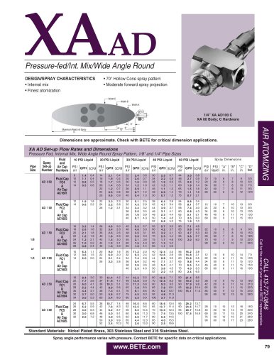 XAAD
XAAD1 Page
 ST
ST1 Page
 XA Components & Options
1 Page
 Custom In-House Fabrications
2 Pages
 BETE Spray Nozzle Catalog
134 Pages
 Line Card
2 Pages
 Bottle, Drum & Tank Washing
16 Pages
 BETE Metric Catalog
132 Pages
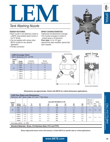
 LEM
LEM1 Page
 NFH
NFH1 Page
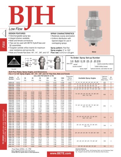 BJH
BJH1 Page
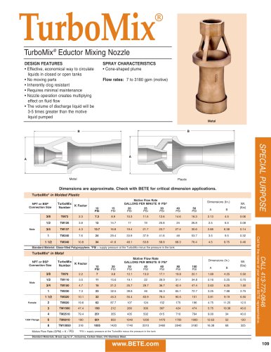 TurboMix
1 Page
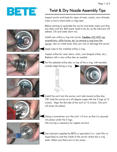
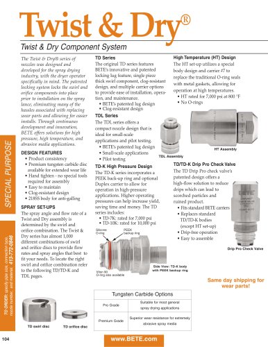 Twist & Dry
5 Pages
 TF29
TF291 Page
 N fire protection
1 Page
 AFF
AFF1 Page
 CLUMP
CLUMP1 Page
 HydroWhirl Orbitor
2 Pages
 HydroWhirl ® Poseidon
1 Page
 HydroWhirl S
1 Page
 SAM
SAM2 Pages
 XA Accessories
4 Pages
 XA
XA7 Pages
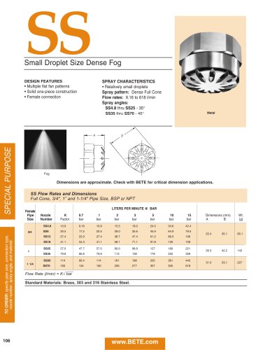
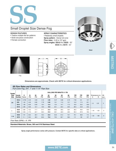 SS
SS1 Page
 UltiMist
1 Page
 L
L1 Page
 p
p1 Page
 PJ
PJ1 Page
 MicroWhirl
1 Page
 SPN
SPN1 Page
 EZ FF NF SPN
2 Pages
 FF
FF2 Pages
 nfs
nfs1 Page
 NFD
NFD1 Page
 NF
NF1 Page
 NFV
NFV1 Page
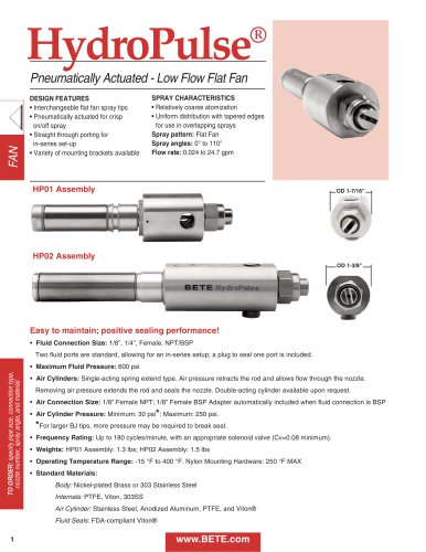 HydroPulse
4 Pages
 BJ
BJ2 Pages
 Spillback
2 Pages
 THW
THW2 Pages
 NCJ
NCJ1 Page
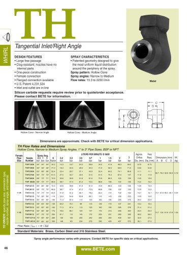
 TH
TH2 Pages
 WTX
WTX2 Pages
 WT
WT2 Pages
 TC
TC1 Page
 NCFL
NCFL1 Page
 NCK
NCK1 Page
 NCS
NCS1 Page
 NC
NC2 Pages
 SF
SF3 Pages
 EZFF
EZFF2 Pages
 WTZ
WTZ1 Page
 CW
CW2 Pages
 WL
WL1 Page
 STXP
STXP1 Page
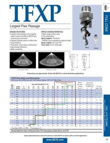 TFXP
TFXP1 Page
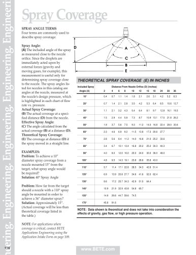 Spray Coverage
1 Page
 Bete accessories
1 Page
 MATERIALS
1 Page
 Custom Lance Intake Sheet
2 Pages
 Pollution Control
8 Pages
 Food Industry
8 Pages
 Fire Protection
8 Pages
 DUR O LOK®
6 Pages
 Chemical Processing
8 Pages
 Spray Nozzle Catalogs
127 Pages
 MaxiPass ® L
1 Page
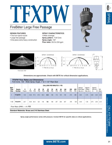 TFXPW
TFXPW1 Page
 N
N2 Pages
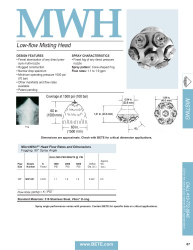 MicroWhirlTM Head (MWH)
1 Page
 MaxiPassTM (MP)
2 Pages
 LP
LP1 Page
 LEM
LEM1 Page
 IS
IS1 Page
 FluidBed
1 Page
 Spray Drying
11 Pages
 Bottle, Drum & Tank Washing
16 Pages
 TD/TD-K
4 Pages
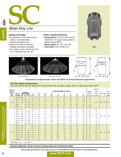 SC
SC2 Pages
 FINZTM
1 Page


Archived catalogs
 SpiralAir
2 Pages
 SpiralAirTM
2 Pages
 TF_2021
1 Page
 TF
TF1 Page
 TW
TW1 Page
 N Fire Protection
2 Pages
 Spray dry manual
25 Pages
- Liquid nozzle
- Stainless steel nozzle
- Cleaning nozzle
- Multi-jet nozzle
- Air nozzle
- Screw-in single nozzle
- Cooling nozzle
- Industrial tip
- Flat tip
- Brass atomizing nozzle
- Plastic nozzle
- Nozzle for the chemical industry
- Full-cone nozzle
- Nozzle for the food industry
- Water nozzle
- Nozzle for the steel industry
- 90° atomizing nozzle
- Washing nozzle
- 60° atomizing nozzle