AURA
1 /8Pages

AURA
1 /8Pages
Catalog excerpts

Installation & Maintenance Instructions WARNING: TO REDUCE THE RISK OF FIRE, ELECTRIC SHOCK, OR INJURY TO PERSONS, OBSERVE THE FOLLOWING: A. Use this unit only in the manner intended by the manufacturer. If you have any questions, contact the manufacturer. B. Before servicing or cleaning unit, switch power off at service panel and lock the service disconnecting means to prevent power from being switched on accidentally. When the service disconnecting means cannot be locked, securely fasten a prominent warning device, such as a tag, to the service panel. C. Installation work and electrical wiring must be done by qualified person(s) in accordance with all applicable codes and standards, including fire-rated construction. D. Sufficient air is needed for proper combustion and exhausting of gases through the flue (chimney) of fuel burning equipment to prevent back drafting. Follow the heating equipment manufacturer’s guideline and safety standards such as those published by the National Fire Protection Association (NFPA), and the American Society for Heating, Refrigeration and Air Conditioning Engineers (ASHRAE), and local code authorities. E. When cutting or drilling into wall or ceiling, do not damage electrical wiring and other hidden utilities. WARNING FOR FUEL BURNING EQUIPMENT: Sufficient air is needed for proper combustion and exhausting of gases through the flue (chimney) of fuel burning equipment to prevent back drafting. Follow the heating equipment manufacturer’s guideline and safety standards such as those published by the National Fire Protection Association (NFPA), and American Society for Heating, Refrigeration and Air Conditioning Engineers (ASHRAE), and local code authorities. UNCRATING This unit was quality inspected and tested immediately prior to packaging and was in operating condition at that time. Check the shipping carton and unit for any damage that may have occurred during shipment. If damage is found, notify the shipping company immediately. The AURA Series air door is shipped completely assembled. Remove the accessory box and the louvered discharge grille (wrapped in protective paper) from the carton. Remove the AURA Series air door from the carton. See Figure 1. Immediately upon unpacking the unit, verify that the rating nameplate agrees with the electric supply available. Do NOT attach the louvered discharge grille or perforated intake grille at this time. BERNER INTERNATIONAL CORPORATION 724-658-3551 © Copyright 2011 Berner International Corporation New Castle, Pennsylvania 1-800-245-4455 • www.berner.com
Open the catalog to page 1
TABLE 1 - Unit Weight .For optimum performance, the bottom of the unit (discharge grille) should be a maximum of 1” above the top of the door opening with the unit mounted flush to the wall. If the unit must be mounted higher, it must be spaced out from the wall 3/8” for every inch the unit is above the door opening (maximum recommended mounting height of 8’). Where possible (installation site permitting), for optimum protection, any void between the air door and the wall should be sealed along the full length of the unit. D. Do not block (obstruct) the air intake grille. Insufficient air flow...
Open the catalog to page 2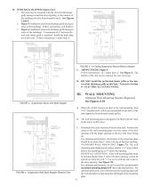
B. WITH BACK ADAPTER: Figures 3 & 4 1. The unit may be mounted with the louvered discharge grille facing toward the door opening, or the interior of the building (electric heated models only). See Figures 3 and 4. 2. Figure 3 installation (louvered discharge grille facing interior of the building). Follow instructions A & B above. 3. Figure 4 installation (louvered discharge grille facing interior of the building). A maximum of 6” between the wall and intake grille is required. Install the back adap tor at this time. Follow instructions 2 under Item A. FIGURE 5 - In-Ceiling Suspension Mount Without...
Open the catalog to page 3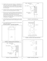
D. Mark the wall in the centers of the (4) ½” round holes provided on the mounting plate. See Figure 6. If the holes on the mounting plate are not located where suitable support is available for the unit, drill new holes in the space provided on the mounting plate. E. Drill the four holes as marked on the wall and attach the mounting plate to the wall (mounting hardware by others). F. Raise the air door with the discharge opening facing down toward the floor. While holding the unit level, slide the heads of the shoulder bolts into the larger hole of the keyhole slots of the mounting plate. Lower...
Open the catalog to page 4
FIGURE - 11 Access Cover Removal F. A wiring guard, See Figure 12, is mounted on the right of the air intake of the unit. The wiring guard is reversible, so it may be mounted on either side of the unit. Remove the ¼” mounting bolt. Clearance holes enable the wiring guard to be removed without disturbing the ¼” shoulder bolts. FIGURE 10 - In-Ceiling Mount With Optional Wall Plate IV.ELECTRICAL CONNECTIONS A. All electrical wiring and connections MUST be performed by qualified personnel in accordance with the National electrical Code ANSI/NFPA No. 70 (latest edition) or, in Canada, the Canadian...
Open the catalog to page 5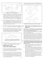
C. Adjust the air directional vanes in the louvered discharge grille so the split location is approximately 3” outside the doorway. FIGURE 13 - Time Delay Adjustment Reinstall the hinged access cover by positioning one hinge into the corresponding catch located on the unit. Raise the other hinge to the unit, when the catch is located press in the hinge and release it into the catch. Swing the access cover into place and align the mounting holes with the threaded inserts on the unit. Reinstall the two ¼” bolts. See Figure 11. M. Attach the perforated intake grille on the ¼” shoulder bolts of the...
Open the catalog to page 6
Use an industrial vacuum or compressed air to remove dirt build-up from the inside of the access cover, air inlet grille, blower wheels/housings, interior of the unit, and heating coils (if applicable). Remove the dirt build-up from the blower wheels through the discharge openings on the blower plate. If the unit is extremely dirty the blower plate (containing the motor and fan wheels) may be removed to further access the internals. C. TO REMOVE THE BLOWER PLATE: 1. Unplug the wiring harness from the motor. 2. Blower plate removal - Remove the four (4) ¼” bolts located on the four corners of...
Open the catalog to page 7All Berner International catalogs and technical brochures
 Hazardous Location Series 20
4 Pages
 Hazardous Location Series 14
5 Pages
 Hazardous Location Series 12
5 Pages
 Industrial Direct Drive 20
4 Pages
 Drive-Thru Unit 3
3 Pages
 Commercial Low Profile 8
3 Pages
 Architectural Recessed 16
3 Pages
 INDUSTRIAL FLY STOP 16
3 Pages
 HAZARDOUS LOCATION
2 Pages
 Industrial Direct Drive 16
2 Pages
 Industrial Direct Drive 12
2 Pages
 INDUSTRIAL BELT DRIVE 16
4 Pages
 ARCHITECTURAL RECESSED 12
3 Pages
 ARCHITECTURAL LOW PROFILE 8
3 Pages
 ARCHITECTURAL ELITE 8
3 Pages
 DTU
DTU6 Pages
 E-ZONE
6 Pages
 VSA /VSB /KSA /KSB
8 Pages
 Door Heaters
4 Pages


- Air curtain
- Air duct
- Horizontal air curtain
- Ambient air curtain
- Flexible air duct
- Ventilation unit
- Ventilation air duct
- Plastic air duct
- Ceiling-mounted air curtain
- Air curtain with electric heating
- Air curtain with water heating
- PVC air duct
- Polyester air duct
- Fabric air duct
- Industrial door air curtain
- Ventilation unit with integrated filtration
- Compact air curtain
- Indoor air curtain
- Panel-mount air curtain
- Outdoor air curtain