
- Catalogs
- BERMAD CS Ltd
- IR Engineering 400

- Company
- Products
- Catalogs
- News & Trends
- Exhibitions
IR Engineering 400

IR Engineering 400
Catalog excerpts

BERMAD Irrigation Basic Valve ??????? IR-400 Basic Valve The basic Model IR-400 diaphragm actuated hydraulically operated valve is at the leading edge of control valve design. It combines simple and reliable construction with superior performance, while at the same time being virtually free of the typical limitations associated with other single chambered valves. These automatic water control valves are designed for vertical or horizontal installation and are available in diameter sizes of 2-16”; DN50- DN400, in a wide range of materials and end connections. The design of the IR-400 valve body includes a full bore seat with unobstructed flow path, free of any in-line ribs, supporting cage, or shafts. The unique hydro-dynamic globe design provides high flow capabilities with minimum head loss. The cover is removable via four (4) fastening bolts (up to 10”) for quick in-line inspection and service. The internal design of the IR-400 valve is based on innovative technology using advanced rubber-based materials to achieve a solid, one piece elastomeric assembly including a flexible fabric reinforced diaphragm, vulcanized with a rugged radial seal disk. The diaphragm is carefully balanced and peripherally supported to avoid distortion and to protect the elastomer, resulting in long-life and controlled actuation even under harsh conditions. One diaphragm and spring fully meet the valve's operating pressure range requirements. The diaphragm assembly can be easily removed from the valve body with no need for disassembling the valve from the line. The Model IR-400 Basic Valve uses valve differential pressure to power the diaphragm assembly open or closed. The lower side of the diaphragm, which serves to cushion the closing of the valve, is exposed to downstream pressure through a dynamic peripheral passageway that its width responds to differential pressure and flow along the downstream side of the valve. The pressure in the control chamber varies, usually resulting from the combined action of a regulating pilot and a fixed orifice. This varying pressure modulates the valve to open or close.
Open the catalog to page 1
400 Series On-Off Modes Closed Position Line pressure applied to the control chamber of the valve creates a hydraulic force that moves the valve to the closed position and provides drip tight sealing. Open Position Discharging the pressure from the control chamber to atmosphere or some other lower pressure zone, causes the line pressure acting on the plug to open the valve. Modulating Closed The restriction continuously allows line pressure into the control chamber. The pilot controls outflow from the control chamber. Throttling when it senses a pressure rise, it causes pressure to accumulate...
Open the catalog to page 2
BERMAD IrrigationPrinciple of Operation3-Way Control Modes Fully Open Position When upstream pressure drops, the pilot blocks the pressure port and opens the drain port, venting the control chamber to the atmosphere. This fully opens the valve, minimizing head loss. Modulating Closed The pilot switches upon pressure rise, blocking the drain port and opening the pressure port. This pressurizes the control chamber, forcing the valve to modulate closed. Locked Position When sensed pressure is equal to setting, the pilot shaft moves and blocks both the drain port and the pressure port. This locks...
Open the catalog to page 3
Product Parts Features 400 Series [1] Fastening Bolts Only four bolts (up to 10"; DN250 valve) fasten valve cover to body, ensuring quick in-line inspection and service. [2] Valve Cover Locates, centralizes and fastens diaphragm and spring ensuring smooth and accurate performance. Simple construction enables quick in-line inspection and service. [3] Auxiliary Closing Spring One single spring fully meets valve requirements for operating pressure range, ensuring low opening pressure and secured closing. [4] Diaphragm Assembly One piece elastomeric assembly that includes a peripherally supported...
Open the catalog to page 4
Technical Data 400 Series Construction Materials [1] [2] [3] [5] Description (1) DN100 & 150 grooved valves are constructed of Ductile Iron (2) Vulcanized Radial Seal Disk Technical Specifications Available Patterns, Size & End Connections G = Globe, A = Angle Connections Standard: Standard Materials: ■ Castings & Forgings: □ Cast Iron to EN 1561 □ Ductile Iron to EN 1563 Flanged: ISO 7005-2 (PN10 & 16) Threaded: Rp ISO 7/1 (BSP.P) or NPT Grooved: ANSI C606 Operating Pressure Ranges: IR-400: 0.5-16 bar For lower pressure requirements, consult factory GR-400: 0.5-10 bar Temperature: Water up...
Open the catalog to page 5
BERMAD Irrigation Globe Pattern [email protected] • www.bermad.com The information herein is subject to change without notice. BERMAD shall not be held liable for any errors. All rights reserved. © Copyright by BERMAD.
Open the catalog to page 6
BERMAD Irrigation 400 Series Flow Charts Globe Pattern 2-Way circuit "Added Head Loss" (for "V" below 2 m/s): 0.3 bar Angle Pattern 2-Way circuit "Added Head Loss" (for "V" below 2 m/s): 0.3 bar 2-Way circuit "Added Head Loss" (for "V" below 2 m/s): 0.3 bar [email protected] • www.bermad.com The information herein is subject to change without notice. BERMAD shall not be held liable for any errors. All rights reserved. © Copyright by BERMAD.
Open the catalog to page 7
Flow Properties Globe Pattern Valve flow coefficient, Kv or Cv Where: Kv = Valve flow coefficient (flow in m3/h at 1bar Diff. Press.) Cv = Valve flow coefficient (flow in gpm at Diff. Press. 1psi) Q = Flow rate (m3/h ; gpm) P = Differential pressure (bar ; psi) Gf = Liquid specific gravity (Water = 1.0) Equivalent Pipe Length, Leq Leq = Lk-D Where: Leq= Equivalent nominal pipe length (m ; feet) Lk = Equivalent length coefficient for turbulent flow in clean commercial steel pipe (SCH 40) D = Nominal pipe diameter (m ; feet) Note: The Leq values given are for general consideration only. 2g Flow...
Open the catalog to page 8
Technical Data 400 Series US English Construction Materials Description (1) 4 & 6" grooved valves are constructed of Ductile Iron (2) Vulcanized Radial Seal Disk Technical Specifications Connections Standard: Flanged: ■ ANSI B16.42 (Cast Iron) ■ ANSI B16.42 (Ductile Iron) Threaded: NPT or Rp ISO 7/1 (BSP.P) Grooved: ANSI C606 Operating Pressure Ranges: IR-400: 7-232 psi For lower pressure requirements, consult factory GR-400: 7-150 psi Temperature: Water up to 140°F Standard Materials: ■ Castings & Forgings: □ Cast Iron to ASTM A-126 Class B □ Ductile Iron to ASTM A-536 □ Brass □ Plastic: Polyamid...
Open the catalog to page 9All BERMAD CS Ltd catalogs and technical brochures
 Model IR-13Q
2 Pages
 Model IR-22T-3W-X
2 Pages
 Model IR-11T-N1-2W
2 Pages
 Model MN-C30
4 Pages
 Model MN-C50
4 Pages
 Model MN-C70
4 Pages
 MONITOR MB3
13 Pages
 Mod. F
14 Pages
 Burkert 6281 Series
1 Page
 Model 42T
4 Pages
 Model 43T
4 Pages
 Model IR-130-59-3W-X
2 Pages
 Model A72
2 Pages
 Air Valves Family
2 Pages
 WW-923-MV
1 Page
 WW-9PM-MV
4 Pages
 Engineering 900
10 Pages
 WW Municipal 720-55
4 Pages
 WW Intro ES-EN
36 Pages
 WW Municipal 723
4 Pages
 WW Municipal 7PM
4 Pages
 WW Municipal 820
4 Pages
 823
8232 Pages
 WW Municipal 720
4 Pages
 700 ES
5 Pages
 Sewage
2 Pages
 Air Valves
4 Pages
 Air Valve C50
4 Pages
 700-2S
4 Pages
 Spare Parts - Waterworks
60 Pages
 700-C2
4 Pages
 Feature code – TC
2 Pages
 DMA Reduced Pressure
1 Page
 IR 43Q
1 Page
 BIC 550
2 Pages
 IR 420-48
2 Pages
 IR 423
2 Pages
 IR 420-55-X
2 Pages
 IR 420-55
2 Pages
 IR 420-XZ
2 Pages
 IR 420
2 Pages
 WW 735-55-M
6 Pages
 WW 735-M
6 Pages
 WW 743
4 Pages
 WW 740Q
6 Pages
 WW 750-65
4 Pages
 WW 750-66-B
4 Pages
 IR 453-66
2 Pages
 IR 450-65-Z
1 Page
 IR 450-60-R
2 Pages
 IR 450-80-XZ
2 Pages
 IR 457-66-U
2 Pages
 Y" Strainer
1 Page
 WW-720
4 Pages
 Model PC3Q
1 Page
 750-80-X
6 Pages
 3-Way Solenoid
1 Page
 3-Way Solenoid
2 Pages
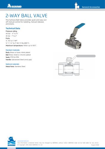 2‑WAY BALL VALVE
1 Page
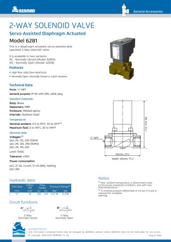 2‑WAY SOLENOID VALVE
1 Page
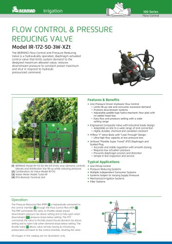 IR‑172‑50‑3W‑XZt
2 Pages
 100 Series Engineering
9 Pages


Archived catalogs
 200 Series Engineering
8 Pages
 170-55-bD Data Sheet
2 Pages
 Air Valves Brochure - IR
4 Pages
 750-66-B IOM
2 Pages
 74Q IOM
2 Pages

