
- Catalogs
- BERMAD CS Ltd
- 74Q IOM

- Company
- Products
- Catalogs
- News & Trends
- Exhibitions
74Q IOM

74Q IOM
The Model 74Q Booster Pump Control Valve is a hydraulically operated, diaphragm-actuated valve that functions as an active check valve. It opens or closes in response to electric signals, isolating the pump from the system during start and stop to prevent surges. In power failure, it acts as a spring-loaded non-return valve.
Installation
1. Ensure adequate space for maintenance.
2. Flush the pipeline before installation.
3. Install isolation gate valves upstream and downstream.
4. Align the valve flow direction with the pipeline flow.
5. Horizontal installation is recommended.
6. Electrical connections must comply with codes and be performed by authorized personnel.
7. Verify solenoid and limit switch specifications.
8. Connect cables according to the electric diagram.
Commissioning & Calibration
1. Open cock valves and isolating valves as specified.
2. Signal the 74Q to open and start the pump slowly.
3. Ensure the discharge line is full and air is released.
4. Program three timers for system control.
5. Test the valve's response to power failure.
Trouble-Shooting
1. For opening issues, check inlet pressure, solenoid, and power supply.
2. For closing issues, check cock valves, solenoid, and control filters.
Preventative Maintenance
1. Regularly check operating conditions.
2. Perform visual and functional inspections.
3. Isolate the valve and vent pressure before maintenance.
4. Stock spare actuator assemblies to minimize downtime.
Spare Parts
Bermad provides a guide for ordering spare parts and components. Refer to solenoid tags for model and serial numbers.
Note
The document is subject to change without notice, and Bermad is not liable for errors.
Catalog excerpts
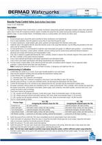
Booster Pump Control Valve, Quick Active Check Valve (Sizes 1½-24"; DN40-600) Description The Model 74Q Booster Pump Control Valve is a double chambered, hydraulically operated, diaphragm actuated, active check valve that opens fully or shuts off in response to electric signals. It isolates the pump from the system during pump starting and stopping, to prevent pipeline surges. In case of power failure, it immediately closes as a spring loaded, zero velocity non return valve. Ensure enough space around the valve assembly for future maintenance and adjustments. Prior to valve installation, flush the pipeline to insure flow of clean fluid through the valve. For future maintenance, install Isolation gate valves upstream and downstream from Bermad control valve. Install the valve in the pipeline with the valve flow direction arrow in the actual flow direction. Use the lifting ring provided on the main valve cover for installing the valve. 5. For best performance, it is recommended to install the valve horizontally and upright. For different valve positions – consult Bermad. 6. System power connections, control cabinet, controller, sensors & wiring must be carried out by authorized electrical engineer / electrician and comply with Electrical and Instrumentation Codes. 7. If the 74Q is ordered & supplied with Bermad BR 740-E controller, forward in advance the schematic diagram of the system with the BR 740-E controller, to the system electrical engineer. 8. Cross-Check solenoid specifications with design requirements and solenoid/coil label. 9. Cross-Check Limit Switch specifications with design requirements and component label. 10. Pull and connect 3-wired cables, to the solenoid and the limit switch, according to electric diagram. Ensure approved cables protection. Confirm that the wires data meet specifications. Note: Energizing the solenoid coil when it is not fixed in its place, is dangerous and might burn the coil. Confirm that cock valves [1], [1.1] and [2] are open (handle parallel to cock-valve body). Open fully the upstream isolating valve and partially the downstream isolating valve Confirm that the 74Q is signaled open: 3.1. Normally Open 74Q: Solenoid is de-energized. 3.2. Normally Closed 74Q: Solenoid is energized or disconnect cover tube fitting to allow 74Q opening. Start the pump and fill-up, in a slow and controlled manner, the discharge line downstream from the system. Confirm the discharge line is full, and that air was released from the line, and open fully the downstream isolating valve. All system constrains, timing & alerts are controlled by the PLC and/or by Bermad BR 740-E controller, which receives the inputs from the system (pump temp., pump power consumption, power supply, main contactors, limit switch position, reservoir level & etc.) and controls the pump & valve accordingly. Three timers need to be programmed: 7.1. td1 = pumps turn-off override command, if valve fails to open. [timer recommended range = 10-180 seconds] 7.2. td2 = delays pump turn-off from limit switch opening (74Q close). [timer recommended range = 1-10 seconds] 7.3. td3 = pumps turn-off override command, if valve failed to close. [timer recommended range = 30-240 seconds] The PLC should operate as follow: N.O. 74Q N.C. 74Q Process Stage Energizing the solenoid closes the 74Q Energizing the solenoid opens the 74Q Pump turn on td1 start counting solenoid energizes, td1 start counting Valve start open limit switch closes contact, td1 stop counting limit switch closes contact, td1 stop counting Turn-of procedure solenoid energizes, td3 start counting solenoid de-energizes, td3 start counting Valve almost closed limit switch opens contact, td2 start counting limit switch opens contact, td2 start counting td2 finishes counting pump turns of, td3 stops counting, solenoid de-energizes pump turns of, td3 stops counting 9. Switch the pump off and confirm the 74Q closes immediately due to its spring loaded check valve function. 10. Check limit switch (S) adjustment. When the valve is closed the limit switch should open the circuit contact. Adjust the limit switch collar as necessary, lowering it to promote pump turn off signal. 11. Switch the pump on. The main valve should start opening. 12. Switch the pump off. The main valve should start closing while the pump is still running. When the valve is fully closed, the collar should push the limit switch to the open contact position, switching the pump off. 13. Note: This test may create negative & positive surge waves along the system, confirm sufficient system surge protection. Simulate a power failure at any point in the operational cycle of the valve by switching off main power supply. The main valve should immediately close.
Open the catalog to page 1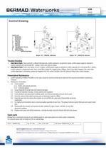
Control Drawing Valve fails to Open: Check pump for sufficient inlet pressure, confirm solenoid is not jammed closed, confirm power supply to solenoid & confirm solenoid coil is not burned (N.C. valves), check cock valve (2) status. Valve fails to Close: Check cock valves (1) & (1.1) status, confirm power supply to solenoid & confirm solenoid coil is not burned (N.O. valves), confirm solenoid is not jammed open, clean control filter & detect for clogged ports or fittings, check if any debris trapped in the main valve, confirm diaphragm is not leaking, release air trapped in the 74Q control chamber...
Open the catalog to page 2All BERMAD CS Ltd catalogs and technical brochures
 Model IR-13Q
2 Pages
 Model IR-22T-3W-X
2 Pages
 Model IR-11T-N1-2W
2 Pages
 Model MN-C30
4 Pages
 Model MN-C50
4 Pages
 Model MN-C70
4 Pages
 MONITOR MB3
13 Pages
 Mod. F
14 Pages
 Burkert 6281 Series
1 Page
 Model 42T
4 Pages
 Model 43T
4 Pages
 Model IR-130-59-3W-X
2 Pages
 Model A72
2 Pages
 Air Valves Family
2 Pages
 WW-923-MV
1 Page
 WW-9PM-MV
4 Pages
 Engineering 900
10 Pages
 WW Municipal 720-55
4 Pages
 WW Intro ES-EN
36 Pages
 WW Municipal 723
4 Pages
 WW Municipal 7PM
4 Pages
 WW Municipal 820
4 Pages
 823
8232 Pages
 WW Municipal 720
4 Pages
 700 ES
5 Pages
 Sewage
2 Pages
 Air Valves
4 Pages
 Air Valve C50
4 Pages
 700-2S
4 Pages
 Spare Parts - Waterworks
60 Pages
 700-C2
4 Pages
 Feature code – TC
2 Pages
 DMA Reduced Pressure
1 Page
 IR 43Q
1 Page
 BIC 550
2 Pages
 IR 420-48
2 Pages
 IR 423
2 Pages
 IR 420-55-X
2 Pages
 IR 420-55
2 Pages
 IR 420-XZ
2 Pages
 IR 420
2 Pages
 WW 735-55-M
6 Pages
 WW 735-M
6 Pages
 WW 743
4 Pages
 WW 740Q
6 Pages
 WW 750-65
4 Pages
 WW 750-66-B
4 Pages
 IR 453-66
2 Pages
 IR 450-65-Z
1 Page
 IR 450-60-R
2 Pages
 IR 450-80-XZ
2 Pages
 IR Engineering 400
12 Pages
 IR 457-66-U
2 Pages
 Y" Strainer
1 Page
 WW-720
4 Pages
 Model PC3Q
1 Page
 750-80-X
6 Pages
 3-Way Solenoid
1 Page
 3-Way Solenoid
2 Pages
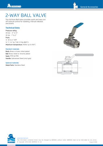 2‑WAY BALL VALVE
1 Page
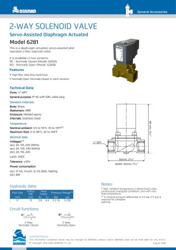 2‑WAY SOLENOID VALVE
1 Page
 IR‑172‑50‑3W‑XZt
2 Pages
 100 Series Engineering
9 Pages


Archived catalogs
 200 Series Engineering
8 Pages
 170-55-bD Data Sheet
2 Pages
 Air Valves Brochure - IR
4 Pages
 750-66-B IOM
2 Pages

