SERIES M
1 /94Pages

SERIES M
1 /94Pages
Catalog excerpts

Series M Helical In-Line Technical Up to - 120 HP / 97,500 lb.in Geared Motors CM-2.00US1211
Open the catalog to page 1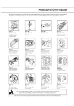
PRODUCTS IN THE RANGE Serving an entire spectrum of mechanical drive applications from food, energy, mining and metal; to automotive, aerospace and marine propulsion, we are here to make a positive difference to the supply of drive solutions. Series A Worm Gear units and geared motors in single & double reduction types Series BD Screwjack worm gear unit Series BS Worm gear unit Series C Right angle drive helical worm geared motors & reducers Series F Parallel angle helical bevel helical geared motors & reducers Series G Helical parallel shaft & bevel helical right angle drive gear units Series...
Open the catalog to page 2
SERIES M CONTENTS General Description Unit Designations Explanation and use of Ratings and Service Factors Selection Procedure For Motorized Units Output Options MOTORIZED Motor Details Motorized Backstop Module Reduction Ratings Thermal Power Ratings Reducer Backstop Module
Open the catalog to page 3
SERIES M GENERAL DESCRIPTION Series M inline geared motors and reducers provide a accumulated design expertise, together with the use result is a series of speed reducing and geared mo- mounted motorized - Base Mounted - B5 (D) Flange Mounted M - Motorized with IEC standard motor mounted motorized mounted motorized * Design Features Include quired. motors. major manufacturers. * fan. As improvements in design are being made continu- in detail and drawings and capacities are subject to sent on request. 1
Open the catalog to page 4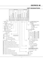
SERIES M UNIT DESIGNATIONS Geared Motor Power Mounting Position Output Shaft Unit Version Revision Version Motor Codes 20 - Additional Gearbox Features 19 - Additional Motor Features 4 - No of Reductions 2 6, 7, 8 - Nominal Overall Ratio eg Base Mounted on Flange Diameter 2 Pole Dual speed or special motor 15, 16, 17 - Geared Motor Powers Motor Power Required M - Motorized with IEC standard motor (IE2) 12 - Motor Adaptor For Unit Types Column 10 Entries M, N, H, E, G or A R - Reducer unit S - Reducer unit with fan kit
Open the catalog to page 5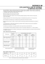
SERIES M EXPLANATION & USE OF RATINGS & SERVICE FACTORS to calculate an equivalent load to compare with catalogue ratings. Mechanical ratings and service factors Fm and Fs uniform load conditions. The unit selected must therefore have a catalogue rating at least equal to half maximum overload. our application engineers. Table 1. Mechanical Service Factor (Fm) Duration of service- Prime mover Moderate mass acceleration factor < 3 mass acceleration factor < 10 Electric motor, steam tur- Uniform mass acceleration factor < 0.2 Mass acceleration factor = all external moments of inertia * moment of...
Open the catalog to page 6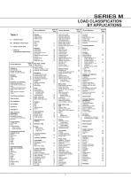
SERIES M LOAD CLASSIFICATION BY APPLICATIONS Driven Machine Driven Machine Cranes main hoists U = Uniform load planer feed chains planer tilting hoist Crusher M = Moderate shock load = Refer to Application Engineering small waste Pumps centrifugal proportioning reciprocating single acting; 3 or small waste maneuvering winches pumps Machine tools rotating, swing or slew tracking, drive wheels Rubber and plastics industries Elevators Blowers centrifugal centrifugal discharge escalators freight pug mill Compressors centrifugal Conveyors-uniformly loaded or fed apron Feeders apron non-reversing group...
Open the catalog to page 7
SERIES M SELECTION PROCEDURE FOR MOTORIZED UNITS 1 Mounting position Running time (%) Uniform load Electric motor, Therefore mechanical service factor (Fm) Motor Frame Size Base Mount Unit Overhung Load Service Factor Motor Frame Size Fm Base Mount Unit Overhung Load Output Speed Service Factor Output Speed Output Torque
Open the catalog to page 8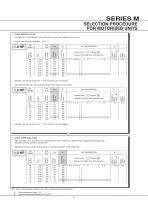
If sprocket, gear, etc is mounted on the outputshaft then refer to Overhung Loads Procedure, page 62, and compare with Fm Base Mount Unit Mass acceleration factor > 10 6 Motor Frame Size Base Mount Unit Motor Frame Size Overhung Load Motor Frame Size Base Mount Unit Overhung Load Service Factor Output Torque Overhung Load Service Factor Output Torque Output Speed Service Factor Output Torque Output Speed Output Speed SELECTION PROCEDURE FOR MOTORIZED UNITS
Open the catalog to page 9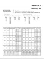
SERIES M UNIT VERSIONS UNIT VERSIONS, COLUMN 9 ENTRY - Base Mounted Flange Mounted Flange Diameter Base and Flange Mounted Flange Diameter Flange Diameter Unit Size Triple Unit Size Triple Flange Diameter
Open the catalog to page 10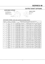
SERIES M OUTPUT SHAFT OPTIONS OUTPUTSHAFT OPTIONS L11* therefore no ‘L11’ dimension is required. OUTPUTSHAFT OPTIONS - double, triple, quadruple and quintuple reduction Inch * Standard Inch * Standard Inch * Standard Inch * Standard Inch * Standard Inch * Standard Inch * Standard Inch * Standard Inch * Standard Inch * Standard Inch * Standard
Open the catalog to page 11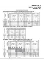
SERIES M MOTOR ADAPTERS NEMA & IEC DOUBLE REDUCTION UNITS NEMA Flanges C Face - Column 12 Entry For Unit Types Column 10 Entries A, E and N Only IEC Flanges B14 - Column 12 Entry For Unit Types Column 10 Entries G, H and M Only IEC Flanges B5 - Column 12 Entry For Unit Types Column 10 Entries G, H and M Only
Open the catalog to page 12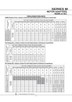
SERIES M MOTOR ADAPTERS NEMA & IEC TRIPLE REDUCTION UNITS NEMA Flanges C Face - Column 12 Entry For Unit Types Column 10 Entries A, E and N Only IEC Flanges B14 - Column 12 Entry For Unit Types Column 10 Entries G, H and M Only IEC Flanges B5 - Column 12 Entry For Unit Types Column 10 Entries G, H and M Only
Open the catalog to page 13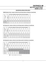
SERIES M MOTOR ADAPTERS NEMA & IEC QUADRUPLE REDUCTION UNITS NEMA Flanges C Face - Column 12 Entry For Unit Types Column 10 Entries A, E and N Only IEC Flanges B14 - Column 12 Entry For Unit Types Column 10 Entries G, H and M Only IEC Flanges B5 - Column 12 Entry For Unit Types Column 10 Entries G, H and M Only
Open the catalog to page 14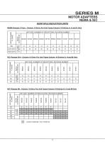
SERIES M MOTOR ADAPTERS NEMA & IEC QUINTUPLE REDUCTION UNITS NEMA Flanges C Face - Column 12 Entry For Unit Types Column 10 Entries A, E and N Only IEC Flanges B14 - Column 12 Entry For Unit Types Column 10 Entries G, H and M Only IEC Flanges B5 - Column 12 Entry For Unit Types Column 10 Entries G, H and M Only
Open the catalog to page 15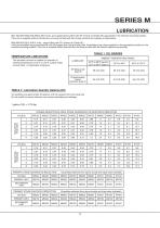
TABLE 1 OIL GRADES TEMPERATURE LIMITATIONS TABLE 2 Lubrication Quantity Gallons (US)
Open the catalog to page 16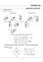
SERIES M MOUNTING POSITIONS COLUMN 13 ENTRY Flange Mounted Units Base Mounted Units Unit Size MOUNTING POSITIONS - SHOWN AS MOTORIZED - APPLIES ALSO FOR REDUCERS 270 o COLUMN 14 ENTRY Terminal Box Position
Open the catalog to page 17All BENZLERS catalogs and technical brochures
 Series X Flexible Couplings
36 Pages
 Roloid Gear Pump
17 Pages
 Series P Planetary
100 Pages
 Benzlers Screw Jacks
69 Pages
 Series J Shaft Mounted Gearbox
73 Pages
 Series P
4 Pages
 Series E
4 Pages
 Compact Motor
4 Pages
 Series J
4 Pages
 Series G flyer
4 Pages
 Benzlers Product Brochure
8 Pages
 BR Series BS
60 Pages
 BR Cone Ring Couplings
16 Pages
 BR Series X Couplings
36 Pages
 BR Series H
123 Pages
 BR Series G
71 Pages
 BR Compact Motors
64 Pages
 BR Series M
120 Pages
 BR Series C
106 Pages
 BR Series K
90 Pages
 BR Series F
117 Pages
 Series BD Screw Jacks
58 Pages
 Elflex Flexible Couplings
8 Pages
 Elign Gear Couplings
17 Pages
 Series X
64 Pages
 Series G
71 Pages
 Geared Motor Series M
120 Pages
 Geared Motor Series C
120 Pages
 Geared Motor Series K
90 Pages
 Geared Motor Series F
119 Pages
- Electric gearmotor
- Planetary gearbox
- Coaxial gearhead
- Precision gearhead
- Right angle gearhead
- Compact gearhead
- Solid-shaft gearhead
- SARRALLE flexible coupling
- SARRALLE shaft coupling
- Gear train gear reducer
- Hollow-shaft gearhead
- Gearbox for industrial applications
- Transmission gearhead
- Right angle electric gearmotor
- Industrial electric gearmotor
- Multi-stage gearhead
- Shaft gearhead
- Single-stage gearhead
- Coaxial gearmotor
- AC gear-motor