

Geared Motor Series M

Geared Motor Series M
- Determine Mechanical Service Factor (Fm): Calculate based on load classification and service duration.
- Determine Required Output Torque: Use the formula: Absorbed power x 9550 / Gearbox output speed.
- Select Geared Motor: Choose a motor size larger than the absorbed power.
- Check Output Torque: Ensure the selected unit's output torque meets requirements.
- Check Service Factor: Verify the adequacy of the service factor.
- Check Overhung Loads: Compare calculated loads with allowable limits.
Catalog excerpts

Series M Helical In-Line Technical Up to - 90kW / 11,000 Nm Geared Motors CM-2.00GB1211
Open the catalog to page 1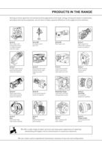
Serving an entire spectrum of mechanical drive applications from food, energy, mining and metal; to automotive, aerospace and marine propulsion, we are here to make a positive difference to the supply of drive solutions. Worm Gear units reduction types Parallel angle helical bevel helical geared motors & reducers Right angle helical bevel helical geared motors & reducers Screwjack worm gear unit Helical parallel shaft & bevel helical right angle drive gear In-line helical geared motors & reducers Worm gear unit Large helical parallel shaft & bevel helical right angle drive units Roloid Gear Pump...
Open the catalog to page 2
ATEX Compliance Assured Total compliance with the ATEX Directive safeguarding the use of industrial equipment in potentially explosive atmospheres is assured for users of our geared products. Certification is available for standard gearboxes and geared motors with badging displaying the CE Mark and the Ex mark, name and location of the manufacturer, designation of series or type, serial number, year of manufacture, Ex symbol and equipment group/category. ATEX directive 94/9/EC (also known as ATEX 95 or ATEX 100A) and the CE Marking Directive are enforced in all EC member states. Compliance is...
Open the catalog to page 3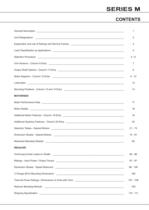
SERIES M CONTENTS General Description ___________________________________________________________________ 1 Unit Designations ____________________________________________________________________ 2 Explanation and use of Ratings and Service Factors _________________________________________ 3 Load Classification by Applications _______________________________________________________ 4 Selection Procedure __________________________________________________________________ 5-6 Unit Versions - Column 9 Entry __________________________________________________________ 7 Output Shaft Options - Column...
Open the catalog to page 5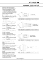
GENERAL DESCRIPTION Series M inline geared motors and reducers provide a very efficient and compact drive solution to meet most requirements up to 90kWwith maximum output torque capacity of 11000Nm. The range takes advantage of many years of accumulated design expertise, together with the use of high quality materials and components. The end result is a series of speed reducing and geared motors offering high load carrying capacity, high efficiency, quiet running and reliability. Twelve sizes of unit with a ratio coverage of 1.4/1 to 70/1 in double reduction and up to 250/1 in triple reduction...
Open the catalog to page 6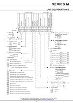
UNIT DESIGNATIONS 6, 7, 8 - Nominal Overall Ratio Base Mounted fj~| - B14 (C) Flange Mounting I V I - Base and B14 (C) Flange Mounting (Non - Standard Special Orders Only) Letter Entry Depends I M I - Motorised with IE2 standard motor Motorised with EPACT standard motor Motorised with IEC high efficiency motor (IE3) Motorised with NEMA high efficiency motor (PREMIUM) Unit to allow fitting of IEC motor (non customer motor) Unit to allow fitting of NEMA motor (non customer motor) Reducer unit Reducer unit with fan kit Reducer unit with backstop CCW rotation Reducer unit with backstop CW rotation...
Open the catalog to page 7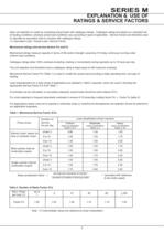
RATINGS & SERVICE FACTORS Gear unit selection is made by comparing actual loads with catalogue ratings. Catalogue ratings are based on a standard set of loading conditions, whereas actual load conditions vary according to type of application. Service Factors are therefore used to calculate an equivalent load to compare with catalogue ratings. i.e. Equivalent Load = Actual Load x Service Factor Mechanical ratings and service factors Fm and Fs Mechanical ratings measure capacity in terms of life and/or strength, assuming 10 hr/day continuous running under uniform load conditions. Catalogue ratings...
Open the catalog to page 8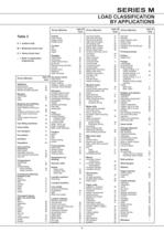
LOAD CLASSIFICATION M = Moderate shock load H = Heavy shock load Driven Machine brew kettles-continuous mash tubs-continuous scale hopper-frequent Clay working clay working machinery M Driven Machine cutter head drives H rotating, swing or slew 1~ tracking, drive wheels 1~ cooling towers light, small diameter U Food industry Laundry washers Line shafts driving processing other line shafts U Lumber industry Driven Machine planer feed chains M planer floor chains M planer tilting hoist M re-saw merry-go-round small waste small waste tipple hoist conveyor M tipple hoist drive M Machine tools punch...
Open the catalog to page 9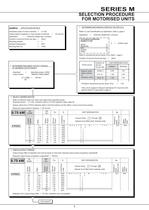
SELECTION PROCEDURE EXAMPLE APPLICATION DETAILS Absorbed power of driven machine = 0.7 kW Output speed of gearbox or Input speed of machine = Application = Uniformly loaded belt conveyor Duration of service (hours per day) = 24hrs 2 DETERMINE REQUIRED OUTPUT TORQUE output torque Gearbox output speed 1 DETERMINE MECHANICAL SERVICE FACTOR (Fm) Referto Load Classification by Application, table 3, page 4 Application = Uniformly loaded belt conveyor Uniform load Refer to mechanical service factor (Fm), table 1, page 3 Duration of service (hours per day) = 24hrs Prime mover Electric motor, steam turbine...
Open the catalog to page 10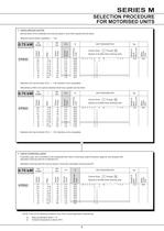
SELECTION PROCEDURE 5 CHECK SERVICE FACTOR Service factor (Fm) of selected unit must be equal or more than required service factor. Required service factor of gearbox = 1.25 Selected unit's service factor (Fm) = 1.48, therefore unit is acceptable. Alternatively a M03 unit could be selected which has a greater service factor Selected unit's service factor (Fm) = 1.94, therefore unit is acceptable. 6 CHECK OVERHUNG LOADS If sprocket, gear, etc is mounted on the outputshaft then refer to Overhung Loads Procedure, page 94, and compare with allowable overhung load (N) of selected unit Allowable overhung...
Open the catalog to page 11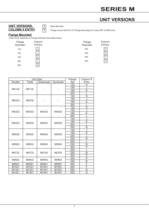
UNIT VERSIONS UNIT VERSIONS. [B] - Base Mounted COLUMN 9 ENTRY j~Ë~| - Flange mount with B14 (C) Flange Mounting (For sizes M01 to M08 only) Flange Mounted Letter Entry Depends on Flange Diameter See tables below Flange Column Flange Column Diameter 9 Entry Diameter 9 Entry
Open the catalog to page 12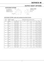
OUTPUT SHAFT OPTIONS OUTPUTSHAFT OPTIONS open ended keyway, Tapped Hole OUTPUTSHAFT OPTIONS - double, triple, quadruple and quintuple reduction
Open the catalog to page 13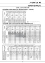
_MOTOR ADAPTERS DOUBLE REDUCTION UNITS IEC Flanges B14 - Column 12 Entry For Unit Types Column 10 Entries G. H and M Only Limited Availability / Non Preferred IEC Flanges B5 - Column 12 Entry For Unit Types Column 10 Entries G. H and M Only UNIT SIZE, NUMBER OF REDUCTIONS, REVISION NUMBER NEMA Flanges C Face - Column 12 Entry For Unit Types Column 10 Entries A. E and N Only UNIT SIZE, NUMBER OF REDUCTIONS, REVISION NUMBER
Open the catalog to page 14All BENZLERS catalogs and technical brochures
 Series X Flexible Couplings
36 Pages
 SERIES M
94 Pages
 Roloid Gear Pump
17 Pages
 Series P Planetary
100 Pages
 Benzlers Screw Jacks
69 Pages
 Series J Shaft Mounted Gearbox
73 Pages
 Series P
4 Pages
 Series E
4 Pages
 Compact Motor
4 Pages
 Series J
4 Pages
 Series G flyer
4 Pages
 Benzlers Product Brochure
8 Pages
 BR Series BS
60 Pages
 BR Cone Ring Couplings
16 Pages
 BR Series X Couplings
36 Pages
 BR Series H
123 Pages
 BR Series G
71 Pages
 BR Compact Motors
64 Pages
 BR Series M
120 Pages
 BR Series C
106 Pages
 BR Series K
90 Pages
 BR Series F
117 Pages
 Series BD Screw Jacks
58 Pages
 Elflex Flexible Couplings
8 Pages
 Elign Gear Couplings
17 Pages
 Series X
64 Pages
 Series G
71 Pages
 Geared Motor Series C
120 Pages
 Geared Motor Series K
90 Pages
 Geared Motor Series F
119 Pages
- Electric gearmotor
- Planetary gearbox
- Coaxial gearhead
- Precision gearhead
- Right angle gearhead
- Compact gearhead
- Solid-shaft gearhead
- Flexible coupling
- Hollow-shaft gearhead
- Shaft shaft coupling
- Gear train gear reducer
- Gearbox for industrial applications
- Transmission gearhead
- Multi-stage gearhead
- Single-stage gearhead
- Shaft gearhead
- Industrial electric gearmotor
- Right angle electric gearmotor
- AC gear-motor
- Coaxial gearmotor