Geared Motor Series K
1 /90Pages

Geared Motor Series K
1 /90Pages
Catalog excerpts

Series K Helical Bevel Technical Up to - 90kW / 12,300 Nm Geared Motors CK-2.00GB1211
Open the catalog to page 1
PRODUCTS IN THE RANGE Serving an entire spectrum of mechanical drive applications from food, energy, mining and metal; to automotive, aerospace and marine propulsion, we are here to make a positive difference to the supply of drive solutions. Series A Worm Gear units and geared motors in single & double reduction types Series BD Screwjack worm gear unit Series BS Worm gear unit Series C Right angle drive helical worm geared motors & reducers Series F Parallel angle helical bevel helical geared motors & reducers Series G Helical parallel shaft & bevel helical right angle drive gear units Series...
Open the catalog to page 2
ATEX Compliance Assured Total compliance with the ATEX Directive safeguarding the use of industrial equipment in potentially explosive atmospheres is assured for users of our geared products. Certification is available for standard gearboxes and geared motors with badging displaying the CE Mark and the Ex mark, name and location of the manufacturer, designation of series or type, serial number, year of manufacture, Ex symbol and equipment group/category. ATEX directive 94/9/EC (also known as ATEX 95 or ATEX 100A) and the CE Marking Directive are enforced in all EC member states. Compliance is...
Open the catalog to page 3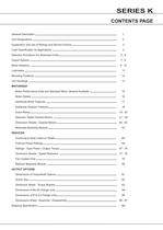
SERIES K CONTENTS PAGE General Description 1 Unit Designations 2 Explanation and use of Ratings and Service Factors 3 Load Classification by Applications 4 Selection Procedure For Motorised Units 5-6 Output Options 7-8 Motor Adaptors 9 - 10 Lubrication 11 Mounting Positions 12 Unit Handings 13 MOTORISED Motor Performance Data and Standard Motor Variants Available 15 Motor Details 16 Additional Motor Features 17 Additional Gearbox Features Exact Ratios Selection Tables Geared Motors Dimension Sheets - Geared Motors Motorised Backstop Module 18 19 - 20 21 - 59 60 - 62 63 REDUCER Overhung & Axial...
Open the catalog to page 5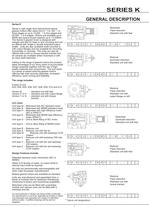
SERIES K GENERAL DESCRIPTION Series K Motorised Series K right angle drive helical bevel helical Triple reduction geared motors offer ratios from 8 : 1 to 160 : 1 in Standard unit with feet three stages or up to 10,000 : 1 in five stages and 36,000 : 1 in 6 stages. Motors are available up to 90kW and output torque capacity up to 12,300Nm. The Series K geared motor is designed with integral cast feet for base or end mounting and can * K 0 8 3 2 5 0 . B M C - 1 B 7 . 5 A - be offered with single or double extended output shafts. Units are also available shaft mounted or with output flanges and...
Open the catalog to page 6
SERIES K UNIT DESIGNATIONS ** Looking on Inputshaft Mounting Position 1 (See page 13 for unit handings) *** Non Standard and Handing - Consult Application Engineering Additional Gearbox Features Additional Motor Features No of Motor Poles Mounting Position Motor Adaptor Output Shaft Type of Unit Unit Version Nominal Overall Ratio Revision Version No of Reductions Size of Unit Series Geared Motor Power Motor Codes Gearbox Codes 1 2 3 4 5 6 7 8 9 10 11 12 13 14 15 16 17 18 19 20 * Example 20 - Additional Gearbox Features Double Oil Seal, Motorised Backstop etc K K 0 8 3 2 5 0 . B M C G 1 D 4 _...
Open the catalog to page 7
SERIES K EXPLANATION & USE OF RATINGS & SERVICE FACTORS Gear unit selection is made by comparing actual loads with catalogue ratings. Catalogue ratings are based on a standard set of loading conditions, whereas actual load conditions vary according to type of application. Service Factors are therefore used to calculate an equivalent load to compare with catalogue ratings. i.e. Equivalent Load = Actual Load x Service Factor Mechanical ratings and service factors Fm and Fs Mechanical ratings measure capacity in terms of life and/or strength, assuming 10 hr/day continuous running under uniform load...
Open the catalog to page 8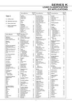
SERIES K LOAD CLASSIFICATION BY APPLICATIONS Driven Machine Table 3 U = Uniform load M = Moderate shock load H = Heavy shock load = Refer to Application Engineering type of load Cranes main hoists bridge travel trolley travel Crusher ore H stone H sugar H Dredges cable reels M conveyors M cutter head drives H jig drives H manoeuvring winches M pumps M screen drive H stackers M utility winches M type of Dry dock cranes load main hoist auxiliary hoist boom, luffing Agitators rotating, swing or slew pure liquids U tracking, drive wheels liquids and solids M liquids-variable density M Elevators bucket-uniform...
Open the catalog to page 9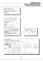
SERIES K SELECTION PROCEDURE FOR MOTORISED UNITS EXAMPLE APPLICATION DETAILS Absorbed power of driven machine = 13kW Output speed of gearbox or Input speed of machine = Application = Uniformly loaded belt conveyor Duration of service (hours per day) = 24hrs Mounting position = 1 Ambient temperature = 20oC Running time (%) = 100% 44rev/min 1 DETERMINE MECHANICAL SERVICE FACTOR (Fm) Refer to Load Classification by Application, table 3, page 4 Application = Uniformly loaded belt conveyor Conveyors-uniformly loaded or fed U apron U assembly U belt U bucket U chain U = Uniform load Refer to mechanical...
Open the catalog to page 10
SERIES K SELECTION PROCEDURE FOR MOTORISED UNITS 4 CHECK OUTPUT TORQUE Output torque (M2) of selected unit must be equal or more than required output torque at gearbox outputshaft. Required output torque at gearbox outputshaft = 2887 Nm 4 POLE 181 97 81 73 67 60 52 46 43 38 8.03 14.94 17.93 20.03 21.61 24.14 27.78 31.67 33.47 38.16 757 1408 1700 1893 2040 2280 2621 3005 3162 3596 3.39 2.68 2.05 1.88 2.03 1.85 1.44 1.26 1.33 1.17 1 Through 20 Spaces to be filled when entering order 34000 K 0 9 3 1 8 . 0 _ M _ - _ _ 1 5 . A - - 272 34000 6 1 . 34000 8 1 . 34000 0 2 . 34000 2 2 . 34000 5 2 . 34000...
Open the catalog to page 11
SERIES K MOTOR ADAPTERS IEC & NEMA TRIPLE REDUCTION UNITS 28. - 125 8.0 - 25. 28. - 125 8.0 - 20. 25. - 125 K0732 8.0 - 25. K0632 36. - 125 K0532 8.0 - 32. K0432 25. - 125 RATIO COVERAGE K0332 8.0 - 20. 71 80 90 100 112 132 UNIT SIZE, NUMBER OF REDUCTIONS, REVISION NUMBER COLUMN 12 ENTRY MOTOR FRAME FLANGE IEC Flanges B14 - Column 12 Entry For Unit Types Column 10 Entries G, H and M Only H B D E E - H K R S S - B D E E - H K R S S - Z B B - E G J L L - Z B B - E G J L L - B B D G J L L N 25. - 125 8.0 - 32. 36. - 125 8.0 - 40. 45. - 160 8.0 - 40. 45. - 160 8.0 - 40. 45. - 100 112 - 160 K1231...
Open the catalog to page 14All BENZLERS catalogs and technical brochures
 Series X Flexible Couplings
36 Pages
 SERIES M
94 Pages
 Roloid Gear Pump
17 Pages
 Series P Planetary
100 Pages
 Benzlers Screw Jacks
69 Pages
 Series J Shaft Mounted Gearbox
73 Pages
 Series P
4 Pages
 Series E
4 Pages
 Compact Motor
4 Pages
 Series J
4 Pages
 Series G flyer
4 Pages
 Benzlers Product Brochure
8 Pages
 BR Series BS
60 Pages
 BR Cone Ring Couplings
16 Pages
 BR Series X Couplings
36 Pages
 BR Series H
123 Pages
 BR Series G
71 Pages
 BR Compact Motors
64 Pages
 BR Series M
120 Pages
 BR Series C
106 Pages
 BR Series K
90 Pages
 BR Series F
117 Pages
 Series BD Screw Jacks
58 Pages
 Elflex Flexible Couplings
8 Pages
 Elign Gear Couplings
17 Pages
 Series X
64 Pages
 Series G
71 Pages
 Geared Motor Series M
120 Pages
 Geared Motor Series C
120 Pages
 Geared Motor Series F
119 Pages
- Electric gearmotor
- Planetary gearbox
- Coaxial gearhead
- Precision gearhead
- Right angle gearhead
- Compact gearhead
- Solid-shaft gearhead
- Flexible coupling
- Gear train gear reducer
- Shaft shaft coupling
- Hollow-shaft gearhead
- Gearbox for industrial applications
- Transmission gearhead
- Industrial electric gearmotor
- Single-stage gearhead
- Right angle gear-motor
- Multi-stage gearhead
- Shaft gearhead
- Coaxial gearmotor
- Compact gear-motor