BR Series K
1 /90Pages

BR Series K
1 /90Pages
Catalog excerpts

Series K Helical Bevel Technical Up to - 90 kW / 12,300 Nm Geared Motors CK-2.00GB1211
Open the catalog to page 1
Certification is available for standard gearboxes and geared motors with badging displaying the CE Mark and the Ex mark, name and location of the manufacturer, designation of series or type, serial number, year of manufacture, Ex symbol and ATEX directive 94/9/EC (also known as ATEX 95 or ATEX 100A) and the CE Marking Directive are enforced in all EC member states. Compliance is compulsory for designers, manufacturers or potentially explosive atmospheres created by the presence of flammable gases, vapours, mists or dusts. Ex compliant standard gearboxes can be supplied against Groups Zones 1...
Open the catalog to page 2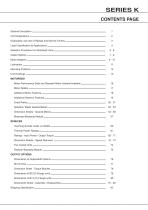
SERIES K CONTENTS PAGE General Description Unit Designations Explanation and use of Ratings and Service Factors Selection Procedure For Motorised Units Output Options Mounting Positions Unit Handings MOTORISED 16 Motor Details Exact Ratios Dimension Sheets - Geared Motors Motorised Backstop Module REDUCER 60 Thermal Power Ratings Ratings - Input Power / Output Torque Dimension Sheets - Speed Reducers Reducer Backstop Module OUTPUT OPTIONS Dimensions of Outputshaft Options Shrink Disc Dimension Sheet - Torque Bracket Dimensions of B5 (D) Flange units Dimensions of B14 (C) Flange units
Open the catalog to page 4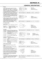
Series K right angle drive helical bevel helical three stages or up to 10,000 : 1 in five stages and 36,000 : 1 in 6 stages. Motors are available up to 90kWand output torque capacity up to 12,300Nm. integral cast feet for base or end mounting and can be offered with single or double extended output shafts. Units are also available shaft mounted or with output flanges and are available for mounting horizontally or vertically. The units can also be offered with a bolt on torque reaction bracket and all variants are available either motorised or with an input shaft assembly. Adding to the range...
Open the catalog to page 5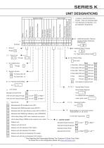
Nominal Overall Ratio -4- Motorised with NEMA standard motor (EPACT) Motorised with IEC high efficiency motor (IE2 or EPACT) Motorised with NEMA high efficiency motor (PREMIUM) Unit to allow fitting of IEC motor (customer own motor) Unit to allow fitting of NEMA motor (customer own motor) suit Application Engineering Additional Gearbox Features Double Oil Seal, Motorised ► Additional Motor Features For Types Without Motor Enter| - | motor types enter Motor Adaptor For Unit Types Column For All Other Types Enter Standard Double Extension Reducer unit with backstop CCW rotation Reducer unit with...
Open the catalog to page 6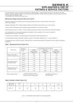
Gear unit selection is made by comparing actual loads with catalogue ratings. Catalogue ratings are based on a standard set of loading conditions, whereas actual load conditions vary according to type of application. Service Factors are therefore used to calculate an equivalent i.e. Equivalent Load = Actual Load x Service Factor Mechanical ratings measure capacity in terms of life and/or strength, assuming 10 hr/day continuous running under Catalogue ratings allow 100% overload at starting, braking or momentarily during operation up to 10 hours per day. Mechanical Service Factor Fm (Table 1)...
Open the catalog to page 7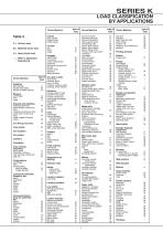
SERIES K LOAD CLASSIFICATION BY APPLICATIONS Driven Machine Driven Machine Cranes main hoists U = Uniform load Crusher ore stone sugar M = Moderate shock load H = Heavy shock load planer feed chains H H H Agitators pure liquids liquids and solids cutter head drives jig drives manoeuvring winches pumps screen drive stackers Pumps centrifugal proportioning reciprocating single acting; 3 or small waste Compressors centrifugal Conveyors-uniformly loaded or fed apron Rubber and plastics industries crackers mixed mills non-reversing group drives individual drives reversing wire drawing and wire winding...
Open the catalog to page 8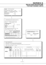
APPLICATION DETAILS Absorbed power of driven machine = 13kW Output speed of gearbox or Input speed of machine = 44rev/min Application = Uniformly loaded belt conveyor Duration of service (hours per day) = 24hrs Ambient temperature DETERMINE MECHANICAL SERVICE FACTOR (Fm) Refer to Load Classification by Application, table 3. Application = Uniformly loaded belt conveyor Refer to mechanical service factor (Fm), table 1, page 3 Duration of service (hours per day) = 24hrs
Open the catalog to page 9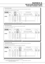
SERIES K SELECTION PROCEDURE FOR MOTORISED UNITS 4 CHECK OUTPUT TORQUE Overhung Load Motor Frame Size Service Factor Output Torque Output Speed Weight of Base Mount Unit Overhung Load Motor Frame Size Service Factor Output Torque Output Speed Weight of Base Mount Unit 6 If sprocket, gear, etc is mounted on the outputshaft then refer to Overhung Loads Procedure and compare with Overhung Load a) Inertia of the Driven Machine (Referred to motor speed) Inertia of Gear Unit plus Motor Motor Frame Size Service Factor Output Torque Output Speed Weight of Base Mount Unit
Open the catalog to page 10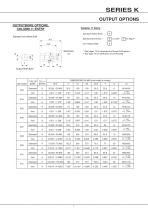
SERIES K OUTPUT OPTIONS OUTPUTBORE OPTIONS, COLUMN 11 ENTRY Column 11 Entry Standard Hollow Shaft Standard / Inch Hollow Shaft m1 m2 * See pages 75 for dimensions of these shaft options Output Shaft Bore Standard Inch
Open the catalog to page 11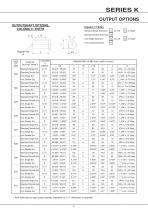
Standard Double Extension | D | Inch Single Extension | N | Inch Double Extension | P | * Inch shaft has an open ended keyway, therefore no 'L11' dimension is required
Open the catalog to page 12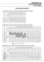
SERIES K MOTOR ADAPTERS IEC & NEMA TRIPLE REDUCTION UNITS IEC Flanges B14 - Column 12 Entry For Unit Types Column 10 Entries G, H and M Only IEC Flanges B5 - Column 12 Entry For Unit Types Column 10 Entries G, H and M Only NEMA Flanges C Face - Column 12 Entry For Unit Types Column 10 Entries A, E and N Only
Open the catalog to page 13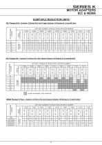
SERIES K MOTOR ADAPTERS IEC & NEMA QUINTUPLE REDUCTION UNITS IEC Flanges B14 - Column 12 Entry For Unit Types Column 10 Entries G, H and M Only IEC Flanges B5 - Column 12 Entry For Unit Types Column 10 Entries G, H and M Only NEMA Flanges C Face - Column 12 Entry For Unit Types Column 10 Entries A, E and N Only
Open the catalog to page 14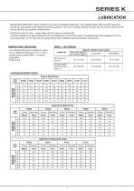
propriate position for the required mounting position (see installation and maintenance instructions) TEMPERATURE LIMITATIONS AMBIENT TEMPERATURE RANGE -5oC to 20oC (type E) 20oC to 50oC 0oC to 35oC -30oC to 20oC (type H) Lubricant Quantities (Litres) TRIPLE REDUCTION Unit Size MOUNTING POSITION QUINTUPLE REDUCTION K0352 Unit Size MOUNTING POSITION QUINTUPLE REDUCTION..CONT K0852 Unit Size MOUNTING POSITION
Open the catalog to page 15All BENZLERS catalogs and technical brochures
 Series X Flexible Couplings
36 Pages
 SERIES M
94 Pages
 Roloid Gear Pump
17 Pages
 Series P Planetary
100 Pages
 Benzlers Screw Jacks
69 Pages
 Series J Shaft Mounted Gearbox
73 Pages
 Series P
4 Pages
 Series E
4 Pages
 Compact Motor
4 Pages
 Series J
4 Pages
 Series G flyer
4 Pages
 Benzlers Product Brochure
8 Pages
 BR Series BS
60 Pages
 BR Cone Ring Couplings
16 Pages
 BR Series X Couplings
36 Pages
 BR Series H
123 Pages
 BR Series G
71 Pages
 BR Compact Motors
64 Pages
 BR Series M
120 Pages
 BR Series C
106 Pages
 BR Series F
117 Pages
 Series BD Screw Jacks
58 Pages
 Elflex Flexible Couplings
8 Pages
 Elign Gear Couplings
17 Pages
 Series X
64 Pages
 Series G
71 Pages
 Geared Motor Series M
120 Pages
 Geared Motor Series C
120 Pages
 Geared Motor Series K
90 Pages
 Geared Motor Series F
119 Pages
- Electric gearmotor
- Planetary gearbox
- Coaxial gearhead
- Precision gearhead
- Right angle gearhead
- Compact gearhead
- Solid-shaft gearhead
- SARRALLE flexible coupling
- SARRALLE shaft coupling
- Gear train gear reducer
- Hollow-shaft gearhead
- Gearbox for industrial applications
- Transmission gearhead
- Right angle electric gearmotor
- Industrial electric gearmotor
- Multi-stage gearhead
- Shaft gearhead
- Single-stage gearhead
- Coaxial gearmotor
- AC gear-motor