

BR Series BS

BR Series BS
Benzler worm gears BS 40-71 feature a symmetrical gear-housing made from aluminum, while BS 88 and 112 use cast-iron. The worm wheel is crafted from centrifugal cast tin-bronze, and the worm screw is case-hardened and ground. Motor connections adhere to IEC standards, ensuring longer lifespan and smoother operation. The worm geared motor can be mounted in any position and combined with other Benzlers gears for low output speeds.
Selection involves calculating service factors based on load type, operating hours, and starts per hour. The document provides formulas for calculating torque and power requirements, ensuring that gear ratings are not exceeded. Service factors and ambient temperature factors are detailed in tables to aid in selection.
The document outlines various mounting positions for the worm geared motors, including horizontal and vertical configurations. It provides execution codes for different configurations, such as hollow shaft and double gears.
Power ratings and output speeds are detailed, with specifications for different motor sizes and configurations. The document includes tables for output torque, permissible overhung load, and service factors for various motor sizes.
The document assures compliance with the ATEX Directive, safeguarding the use of industrial equipment in potentially explosive atmospheres, ensuring safety for users of geared products.
The document lists various series of gear units and motors, including Series X, J, C, BD, G, M, H, and others, each with specific features and applications.
The document describes the conversion of an aluminium surface into aluminium oxide through a chemical process, resulting in a hard, ceramic finish. It includes specifications for various gear models (BS 40, BS 50, BS 63, BS 71) with details on maximum and minimum dimensions and output speeds.
Mounting Procedures:
1. Gears should be placed on a flat, solid foundation and not mounted with force to avoid damage.
2. Proper alignment of the gear and driven machine is crucial to prevent increased load on shafts and bearings.
3. Gears must be protected from heat, dust, and damp conditions while ensuring adequate cooling air circulation.
Lubrication and Maintenance:
1. Benzler worm gears are pre-filled with synthetic oil and are maintenance-free.
2. Gears should be run under low load for the first 10-30 hours, gradually increasing to full load.
3. Oil and gear temperatures up to 100°C are safe; special seal rings are needed if temperatures exceed this.
4. Gears not in use should be run periodically to prevent deterioration.
Safety and Installation Guidelines:
1. Fire and explosion risks must be managed with appropriate precautions.
2. Rotating shafts and couplings should be guarded to prevent physical contact.
3. Proper lifting techniques must be used to avoid injury.
4. Only approved tools and spare parts should be used for maintenance.
Contact Information:
The document provides contact details for Benzlers and Radicon offices across various countries including Australia, Europe, Denmark, Finland, India, Sweden, Norway, Thailand, the United Kingdom, and the USA.
Catalog excerpts

rodicon** benzlers* with you at every turn with you at every turn Series BS Compact Worm Gear
Open the catalog to page 1
PRODUCTS IN THE RANGE Serving an entire spectrum of mechanical drive applications from food, energy, mining and metal; to automotive, aerospace and marine propulsion, we are here to make a positive difference to the supply of drive solutions. Series A Worm Gear units and geared motors in single & double reduction types Series BD Screwjack worm gear unit Series BS Worm gear unit Series C Right angle drive helical worm geared motors & reducers Series F Parallel angle helical bevel helical geared motors & reducers Series G Helical parallel shaft & bevel helical right angle drive gear units Series...
Open the catalog to page 2
Total compliance with the ATEX Directive safeguarding the use of industrial equipment in potentially explosive atmospheres is assured for users of our geared products. Certification is available for standard gearboxes and geared motors with badging displaying the CE Mark and the Ex mark, name and location of the manufacturer, designation of series or type, serial number, year of manufacture, Ex symbol and equipment group/category. ATEX directive 94/9/EC (also known as ATEX 95 or ATEX 100A) and the CE Marking Directive are enforced in all EC member states. Compliance is compulsory for designers,...
Open the catalog to page 3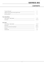
Technical information ___________________________________________________________ Selection of worm gears and worm geared motors ____________________________________ Mounting positions _____________________________________________________________ Worm Geared Motors Power ratings - Output speeds ___________________________________________________ Worm Gears Power ratings - Output speeds ___________________________________________________
Open the catalog to page 5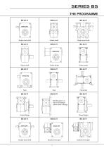
Single input shaft Hollow shaft Single input shaft Output shaft Hollow shaft Bolt the gear to a wall or foundation Double input shaft Double worm gear Double worm gear
Open the catalog to page 6
Benzlerworm gears BS 40-71 have a symmetrical gear-housing manufactured in aluminium. BS 88 and 112 have a gearhousing of cast-iron. The worm wheel is made of centrifugal cast tinbronze and the worm screw is case-hardened and ground. All motor connections are according to lEC-standard and for BS 40-112 with elastic coupling. This means • The worm screw is mounted with two separate bearings and are not connected with the motor bearings. This means longer lifetime and a smoother drive.. • Soft start and stop with elastic coupling for size • Possibility to change motor without dismounting • Any...
Open the catalog to page 7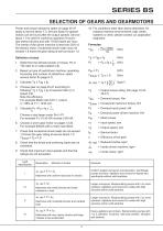
Power and torque ratings for gears on page 40-47 apply to service factor 1.0. Service factor for geared motors can be found after the output speeds. Service factor 1.0 is valid for continous operation 8 hours/ day without shocks and with 10-200 starts per hour. The inertia of the driven machine is less than 20% of the electric motor. Occasional shock loads may not exceed 1.8 times the gear rating at service factor 1.0. 1. Determine the demand power or torque, Pe or T2b ratio (i) or output speed (n2). 2. Based on type of load/driven machine, operating hours/day and number of starts/hour, select...
Open the catalog to page 8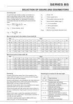
Overhung load If a sprocket, gearwheel or pulley is mounted on a shaft, a load check must be made. The overhung load in middle of the shaft may not exceed values shown in tables below. For calculation of minimum permissible diameter the following formula should be Max overhung load in the middle of input shaft (N) Ff2 = Permissible overhung load (N) fb = Service factor (tables page 7) Dmin = Minimum permissible diameter (mm)
Open the catalog to page 10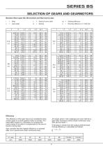
Benzlers Worm gear BS, Wormwheel and Wormscrew data z = Starts of worm shaft
Open the catalog to page 11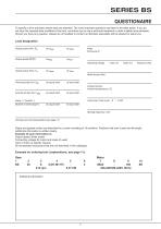
To specify a drive precisely certain data are essential. The most important questions are listed in the table below. If you do not have the required data available in this form, we advice you to use a technical handbook or other suitable documentation. Should you have any question, please do not hesitate to contact us, Benzlers specialists will be pleased to assist you. Load designation Output power (kW): Pe at nmax at nmjn Motor Output speed (RPM): nemax nemin Operating voltage motor (V) brake (V) frequency (Hz) Output torque (Nm): Te at nmax at nmjn Overhung load (N): Fr2e at output shaft at...
Open the catalog to page 12
BS (Worm gear and worm geared motor) Other combinations and sizes can be achieved. Check with Benzlers. See picture *For execution - code 2 and 3 state flange size, for example M=115, see page 55. VM = distance ring for different position of terminal box KEB = coupling/brake unit (specify type and voltage) DP = double input shaft 2 = free high speed shaft (no motor or flange for 3 = prepared for motor (specify flange and shaft diametres or I EC-standard size) FS = Fitted with forced cooling Motor sizes * = Can be changed to 0 with distance ring, VM + = Distance ring to be mounted on gear
Open the catalog to page 13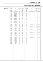
SERIES BS WORM GEARED MOTORS 0.12 kW Permissable overhung load Fr2 kN
Open the catalog to page 14
SERIES BS WORM GEARED MOTORS 0.18 kW Permissable overhung load Fr2 kN
Open the catalog to page 15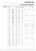
SERIES BS WORM GEARED MOTORS 0.25 kW Permissable overhung load Fr2 kN
Open the catalog to page 16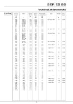
SERIES BS WORM GEARED MOTORS 0.37 kW Permissable overhung load Fr2 kN
Open the catalog to page 17
SERIES BS WORM GEARED MOTORS 0.55 kW Permissable overhung load Fr2 kN
Open the catalog to page 18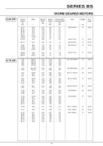
SERIES BS WORM GEARED MOTORS 0.55 kW Permissable overhung load Fr2 kN
Open the catalog to page 19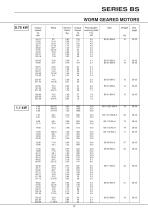
SERIES BS WORM GEARED MOTORS 0.75 kW Permissable overhung load Fr2 kN
Open the catalog to page 20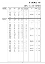
SERIES BS WORM GEARED MOTORS 1.1 kW Permissable overhung load Fr2 kN
Open the catalog to page 21
SERIES BS WORM GEARED MOTORS Output speed n2 rpm 14.76 Permissable overhung load Fr2 kN
Open the catalog to page 22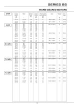
SERIES BS WORM GEARED MOTORS 3 kW Permissable overhung load Fr2 kN
Open the catalog to page 23
Worm geared motors BS40-112 Shaftmounted Mounting position O, hollow shaft Position of terminal box, see page 11 Shaft tolerance, see page 57 Motor- Motor dimensions Gear unit dimensions
Open the catalog to page 24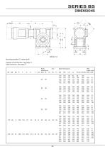
Mounting position O, hollow shaft Position of terminal box, see page 11 Shaft tolerance, see page 57
Open the catalog to page 25
Worm geared motors BS40-112 Footmounted Position of terminal box, see page 11 Shaft tolerance, see page 57 Motor- B14 B5 Gear unit dimensions size Motor dimensions
Open the catalog to page 26All BENZLERS catalogs and technical brochures
 Series X Flexible Couplings
36 Pages
 SERIES M
94 Pages
 Roloid Gear Pump
17 Pages
 Series P Planetary
100 Pages
 Benzlers Screw Jacks
69 Pages
 Series J Shaft Mounted Gearbox
73 Pages
 Series P
4 Pages
 Series E
4 Pages
 Compact Motor
4 Pages
 Series J
4 Pages
 Series G flyer
4 Pages
 Benzlers Product Brochure
8 Pages
 BR Cone Ring Couplings
16 Pages
 BR Series X Couplings
36 Pages
 BR Series H
123 Pages
 BR Series G
71 Pages
 BR Compact Motors
64 Pages
 BR Series M
120 Pages
 BR Series C
106 Pages
 BR Series K
90 Pages
 BR Series F
117 Pages
 Series BD Screw Jacks
58 Pages
 Elflex Flexible Couplings
8 Pages
 Elign Gear Couplings
17 Pages
 Series X
64 Pages
 Series G
71 Pages
 Geared Motor Series M
120 Pages
 Geared Motor Series C
120 Pages
 Geared Motor Series K
90 Pages
 Geared Motor Series F
119 Pages
- Electric gearmotor
- Planetary gearbox
- Coaxial gearhead
- Precision gearhead
- Right angle gearhead
- Compact gearhead
- Solid-shaft gearhead
- Flexible coupling
- Hollow-shaft gearhead
- Shaft shaft coupling
- Gear train gear reducer
- Gearbox for industrial applications
- Transmission gearhead
- Multi-stage gearhead
- Single-stage gearhead
- Industrial electric gearmotor
- Right angle electric gearmotor
- AC gear-motor
- Coaxial gearmotor
- Shaft gearhead