BR Cone Ring Couplings
1 /16Pages

BR Cone Ring Couplings
1 /16Pages
Catalog excerpts
benzlers* radicon*' with you at every turn with you at every turn Series X Cone Ring Flexible Couplings Flexible Couplings
Open the catalog to page 1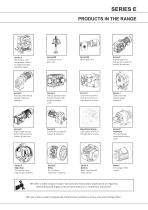
PRODUCTS IN THE RANGE PRODUCTS IN THE RANGE Serving an entire spectrum of mechanical drive applications from food, energy, mining and metal; to automotive, aerospace and marine propulsion, we are here to make a positive difference to the supply of drive solutions. Series A Worm Gear units and geared motors in single & double reduction types Series BD Screwjack worm gear unit Series BS Worm gear unit Series C Right angle drive helical worm geared motors & reducers Series F Parallel shaft helical geared motors & reducers Series G Helical parallel shaft & bevel helical right angle drive gear units...
Open the catalog to page 2
SERIES X - CONE RING CONTENTS PAGE General Information / Reference Notes Selection Procedure CONE RING General Description Unit Designations Dimensions & Specifications Engineering Data Recommended Bores - Metric and Inch Misalignment Capacities
Open the catalog to page 3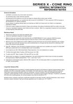
SERIES X - CONE RING GENERAL INFORMATION REFERENCE NOTES General Information - Inch/Metric conversions may not be direct conversions. - Our standards apply unless otherwise specified. - All Dimensions are for reference only and are subject to change without notice unless certified. - Unless otherwise specified, our coupling hubs will be bored for CLEARANCE FIT with a setscrew OVER the keyway or INTERFERENCE FIT without a setscrew. - Torque ratings of couplings utilising Taper-Lock bushings can differ from those that do not. Refer to our Applicaion t Engineers for details. - If we are to supply...
Open the catalog to page 4
SERIES X - CONE RING SELECTION PROCEDURE Standard Selection Method Formula Selection Method The standard selection method can be used for most motor, turbine, or engine driven applications. The following information is required to select a gear coupling. The Standard Selection Method can be used for most coupling selections. The procedure below should be used for: • High Peak Loads • Brake Applications (where the disc brake or brakewheel is to be an integral part of the coupling, consult our Application Engineers for design options). • Application or type of equipment to be connected (motor to...
Open the catalog to page 5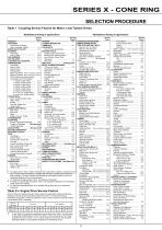
Alphabetical listing of applications For engine drives, refer to Table 2. Electric motors, generators, engines, compressors and other machines fitted with sleeve or straight roller bearings, usually require limited end float couplings. If in doubt, provide axial clearances and centering forces to one of our Application Engineers for a recommendation. For balanced opposed design, refer to our Application Engineers. If people are occasionally transported, refer to our Application Engineers for the selection of the proper size coupling. For high peak load applications (such as Metal Rolling Mills)...
Open the catalog to page 6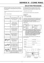
SERIES X - CONE RING SELECTION PROCEDURE SERVICE FACTORS: are a guide, based on experience of the ratio between coupling catalogue rating and system characteristics. The following information is necessary to quote or ship to your characteristics. exact requirements. Prompt service is assured if this informaion is given on your inquiry or order. t The system characteristics are best measured with a torque meter. 1. Application: Driver & Driven Table 3 . Service Factors 3. Speed (RPM) 4. Quantity 5. Coupling Size and Type, e. g., Size 1070G20 Torque Demands Driven Machine Typical applications...
Open the catalog to page 7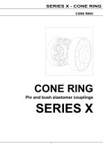
SERIES X - CONE RING CONE RING CONE RING Pin and bush elastomer couplings
Open the catalog to page 8
SERIES X - CONE RING GENERAL DESCRIPTION Cone Ring Couplings Pin and bush elastomer Couplings 611 Heavy Duty Straight Bored 613 Heavy Duty Taper Bushed 612 Medium Duty Straight Bored 614 Medium Duty Taper Bushed General Description Types Available Flexible Cone Ring couplings, types 61,612,613, 614 are available with bore sizes up to 355 mm diameter and a basic rated torque up to 188700 Nm. Two options are available, MEDIUM DUTY and HEAVY DUTY. Operational Details They accommodate all types of shaft misalignment met in normal operation, being a development of the old pin and bush design which...
Open the catalog to page 9
SERIES X - CONE RING UNIT DESIGNATIONS Additional Features Driven Hub Bore Diameter Driven Hub Bore & Keyway Driving Hub Bore Diameter Driving Hub Bore & Keyway Cone Ring Flexible Coupling StraightBored, Heavy Duty Cone Ring Flexible Coupling Bored for taper lock bush, Medium Duty 12, 13, 14 - Driven Hub Bore Diameter Reference 7 - Driving Hub Bore and Keyway 11 - Driven Hub Bore and Keyway M - Metric Bore Parallel Keyway T - Metric Bore Taper Keyway T - Metric Bore Taper Keyway I - Inch Bore Parallel Keyway I - Inch Bore Parallel Keyway B - Inch Bore Taper Keyway B - Inch Bore Taper Keyway -...
Open the catalog to page 10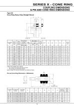
SERIES X - CONE RING COUPLING DIMENSIONS & PIN AND CONE RING DIMENSIONS Type 611 Cone Ring Heavy Duty Straight Bored E E Driving Half Driven Half Coupling Size Coupling Weight With No Bore (kg) Min. Bore * Hub Max. Driving Driven length Bore E Half Half Larger sizes available upon request. * Up to size 05 the driving half hubs are solid. ** The coupling pin withdrawal distance. Refer to Page 4 for General Information and Reference Notes. M M Pin and Cone Ring Dimensions - Millimeters) Coupling Pin Assembly size Number 01 - 02 Cone Ring Number Max Bolt Tightening Torque (Nm)
Open the catalog to page 11
SERIES X - CONE RING COUPLING DIMENSIONS & PIN AND CONE RING DIMENSIONS Type 613 Cone Ring Heavy Duty Taper Bushed E E Driving Half Driven Half Coupling Size Coupling Weight With No Bore (kg) Hub Hub Min. length length Bore * E T Not available as taper bushed ** The coupling pin withdrawal distance. Refer to Page 4 for General Information and Reference Notes. M M Pin and Cone Ring Dimensions - Millimeters) J J Coupling Pin Assembly size Number 01 - 02 Cone Ring Number Max Bolt Tightening Torque (Nm)
Open the catalog to page 12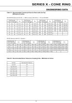
SERIES X - CONE RING ENGINEERING DATA Table 19 - Recommended Commercial Keys for Bores with One Key Millimeters & Inches MILLIMETERS (Bores per ISO 286 - 2 - 1988 (E), Keyway to BS 4235 pt 1 : 1972 and DIN 6885) Shaft Diameter Over Shaft Diameter Over Shaft Diameter Over Shaft Diameter INCHES (Bores per ANSI B17.1 Standard) Shaft Diameter Over Shaft Diameter Over Shaft Diameter Shaft Diameter Table 20 - Recommended Bores Tolerances Coupling Hubs - Millimeters & Inches Nominal Bore Diameter Tolerance
Open the catalog to page 13All BENZLERS catalogs and technical brochures
 Series X Flexible Couplings
36 Pages
 SERIES M
94 Pages
 Roloid Gear Pump
17 Pages
 Series P Planetary
100 Pages
 Benzlers Screw Jacks
69 Pages
 Series J Shaft Mounted Gearbox
73 Pages
 Series P
4 Pages
 Series E
4 Pages
 Compact Motor
4 Pages
 Series J
4 Pages
 Series G flyer
4 Pages
 Benzlers Product Brochure
8 Pages
 BR Series BS
60 Pages
 BR Series X Couplings
36 Pages
 BR Series H
123 Pages
 BR Series G
71 Pages
 BR Compact Motors
64 Pages
 BR Series M
120 Pages
 BR Series C
106 Pages
 BR Series K
90 Pages
 BR Series F
117 Pages
 Series BD Screw Jacks
58 Pages
 Elflex Flexible Couplings
8 Pages
 Elign Gear Couplings
17 Pages
 Series X
64 Pages
 Series G
71 Pages
 Geared Motor Series M
120 Pages
 Geared Motor Series C
120 Pages
 Geared Motor Series K
90 Pages
 Geared Motor Series F
119 Pages
- Electric gearmotor
- Planetary gearbox
- Coaxial gearhead
- Precision gearhead
- Right angle gearhead
- Compact gearhead
- Solid-shaft gearhead
- SARRALLE shaft coupling
- Gear train gear reducer
- Hollow-shaft gearhead
- Gearbox for industrial applications
- Transmission gearhead
- Right angle electric gearmotor
- Industrial electric gearmotor
- Multi-stage gearhead
- Shaft gearhead
- Single-stage gearhead
- Coaxial gearmotor
- AC gear-motor