- Catalogs
- Bentone - Enertech AB
- Bentone BG450 LN
Bentone BG450 LN
1 /48Pages

Bentone BG450 LN
1 /48Pages
Catalog excerpts

Providing sustainable energy solutions worldwide Installation- and maintenance instruction
Open the catalog to page 1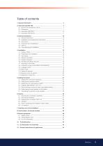
Table of contents 1. General Information _____________________________________________ 4 2. Technical data BG 550... _________________________________________ 7 2.1 Burners are intended for use at: ________________________________ 7 2.2 Dimensions _________________________________________________ 7 2.3 Description BG 550-2 _______________________________________ 10 2.4 Description BG 550 M _______________________________________ 11 3. General instruktions ____________________________________________ 3.1 General instructions _________________________________________ 3.2 Installation and maintenance...
Open the catalog to page 3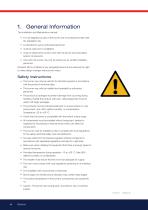
1. General Information This Installation and Maintenance manual: • is to be regarded as part of the burner and must always be kept near the installation site • is intended for use by authorised personnel • must be read prior to installation • must be observed by all who work with the burner and associated system components • work with the burner may only be carried out by certified installers/ personnel Enertech AB is not liable for any typographical errors and reserves the right to make design changes without prior notice. Safety instructions • The burner may only be used for its intended purpose...
Open the catalog to page 4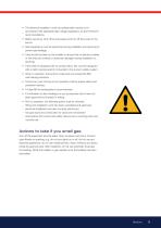
• The electrical installation must be professionally carried out in accordance with applicable high voltage regulations, as per Enertech's recommendations. • Before servicing, shut off the fuel supply and turn off the power to the burner. • Seal inspections must be performed during installation and servicing to prevent gas leakage. • Care should be taken by the installer to ensure that no electrical cables or fuel lines are crushed or otherwise damaged during installation or servicing. • If the boiler is equipped with an access hatch, this must be equipped with a hatch opening switch connected...
Open the catalog to page 5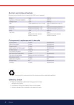
Servicing must be carried out once a year or after 3000 hours of operation Contactor 10 years 500,000 starts The burner and its components must be recycled according to applicable regulations. Delivery check • Make sure everything is delivered and the goods have not been damaged during transit. • If something is wrong with a delivery, report it to the supplier. • Transport damage must be reported to the shipping company.
Open the catalog to page 6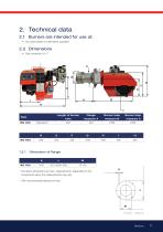
2.1 Burners are intended for use at: • Hot water boilers in intermittent operation 2.2 Dimensions • Gas connection %-2” * The above dimensions are max. measurements. Depending on the components used, the measurements may vary. ** Min. recommended distance to floor.
Open the catalog to page 7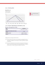
I Do not exceed working H field Measurements according to EN 3746: 2010 Alt. 1 The sound level of the burner can be reduced by equipping the burner with silencer. Installation must be done so it does not prevent air supply to the burner. Alt.2 The burner's noise level can be reduced by connecting the burner's air intake to the air duct that opens into an appropriate location. Installation must be done so it does not prevent air supply to the burner.
Open the catalog to page 9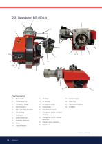
Components 1. Burner tube 21. Damper motor 22. Relay box 23. Electrical connection 24. MultiBloc 17. Changeover switch, increase-decrease 18. Changeover switch, manual-automatic 19. Indicator lamp, operation
Open the catalog to page 10
3. General instruktions 3.1 General instructions The installation of the gas burner must be carried out in accordance with current regulations and standards. The installers of gas burners should therefore be acquainted with all regulations and ensure that the installation complies with the requirements. The installation, mounting and adjustment should be made with the greatest care and only the correct gas should be used. 3.2 Installation and maintenance instructions The maintenance instructions supplied with the burner must be kept at an easily accessible location in the boiler room. 3.3 Instructions...
Open the catalog to page 11
4. Installation 4.1 Delivery check Check that all has been delivered and that the goods have not been damaged during transport. If that is not the case, please notify the delivery company. Transport damages should be reported to the forwarding agency. 4.2 Preparations for installation Check that the measurements and capacity range of the burner are compatible with the boiler. The power ratings on the type plate refer to the min. and max. power of the burner. 4.3 Gas supply For good operating safety, it is important that the gas supply system is installed correctly. Consider the following: 1....
Open the catalog to page 12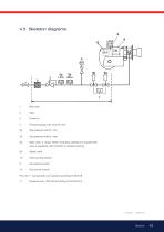
4. Pressure gauge with shut-off cock 5a. Gas pressure switch, mini 5b. Gas pressure switch, maxi 6a. Main valve, 2 -stage. When modulaing operation is required this valve is equipped with controls for variable opening. 6b. Safety valve 1)7. Valve proving system Pos. 5b, 7: Components not required according to EN 676. 1) Required over 1200 kW according to EN 676.hhh
Open the catalog to page 13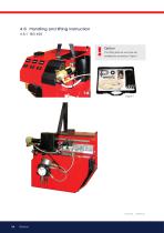
Option The lifting aids we use here are available as accessory, Figure 1
Open the catalog to page 14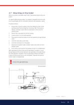
4.7 Mounting on the boiler Mount the burner to the boiler using 4 bolts. See technical data for the hole pattern. To make the fitting process easier, it is possible to separate the burner body from the gas flange with the combustion head and valve assembly in place. Proceed as follows: 1. Ensure that no power is going to the burner. Break the main current and disconnect the Euro plugs from the burner. NB: If the burner is directly connected, ensure that all components on the burner are without power. Remove the cover plate from the fan housing. Loosen screw D on the nozzle assembly. Disconnect...
Open the catalog to page 15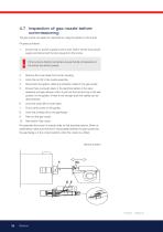
4.7 Inspection of gas nozzle before commissioning The gas nozzle can easily be inspected by using the guides on the burner. Proceed as follows: 1. Ensure that no power is going to the burner. Switch off the main power supply and disconnect the Euro plugs from the burner. If the burner is directly connected, ensure that all components on the burner are without power. Remove the cover plate from the fan housing. Undo the nut (D) to the nozzle assembly. Disconnect the ignition cable and ionisation cable for the gas nozzle. Ensure there is enough slack in the electrical cables to the valve assembly...
Open the catalog to page 16All Bentone - Enertech AB catalogs and technical brochures
 Bentone B55
2 Pages
 Bentone B2 Classic
2 Pages
 Bentone B45-B55-B65
28 Pages
 Bentone B30-B40
24 Pages
 Fantastic History Amazing Future
12 Pages
 Bentone B45i A2.2H
108 Pages
 Bentone B65
2 Pages
 Bentone B45A
2 Pages
 Bentone B 45-2 MF
2 Pages
 Bentone B40A
2 Pages
 Bentone B30A
2 Pages
 Bentone B1 Classic
2 Pages
 Bentone B65-2 RME
2 Pages
 Bentone B70/B80
2 Pages
 Bentone BF1
2 Pages
 Bentone BF1 HC
2 Pages
 Bentone BF1 RME
2 Pages
 Bentone BF1-2
2 Pages
 Bentone BF1-2 HC
2 Pages
 Bentone BFG1
2 Pages
 Bentone BFG1 HC
2 Pages
 Bentone BFG1 LN
2 Pages
 Bentone BFG1-2
2 Pages
 Bentone BFG1-2 HC
2 Pages
 Bentone BG300/BG400
2 Pages
 Bentone BG450
2 Pages
 Bentone BG550/BG650
2 Pages
 Bentone BG700/BG800
2 Pages
 Bentone ST133/146
2 Pages
 Bentone STG 146
2 Pages
 Bentone BG950 500 - 3200 kW
2 Pages


