
- Catalogs
- Bentone - Enertech AB
- Bentone B45i A2.2H


Bentone B45i A2.2H

Bentone B45i A2.2H
This manual is crucial for the installation and maintenance of the B 45i A2.2H burner, intended for authorized personnel only. It must be kept near the installation site and used solely for its intended purpose. Enertech AB is not responsible for typographical errors and reserves the right to make design changes without notice. Compliance with local fire, electrical, and fuel distribution regulations is mandatory.
The B 45i A2.2H burner is designed for light oil and B10 heating oil/biofuel blend, suitable for various heating applications. It operates within a range of 8.5-45.5 kg/h and 101-540 kW.
Installation requires careful handling, acceptance inspection, and preparation. The burner must be mounted on the boiler with proper electrical connections and oil distribution, ensuring the site is free of chemicals and has adequate air supply.
Settings involve adjusting the combustion assembly, air pressure switch, and nozzle assembly. Regular servicing is required annually or after 3000 hours of operation. Key components have a recommended service life of 10 years or 250,000 cycles.
Common issues include the burner not starting or delayed ignition. The LMV37 automatic control unit manages operations, with detailed instructions for setting, backup, and fault status messages.
Safety measures include using hearing protection due to noise levels exceeding 85 dBA and ensuring no damage to electrical cables or fuel lines during installation. A Class BE fire extinguisher is recommended. Regular maintenance includes checking for leaks and ensuring all safety devices are operational.
Components like the burner, filter, oil hose, and nozzle require annual replacement or cleaning. Recycling must comply with applicable regulations.
- Ensure no damage to electrical cables or fuel/gas pipes during installation or maintenance.
- Maintenance instructions must be accessible in the boiler room.
- Users should receive detailed instructions on the oil burner and system functionality.
- Regular inspection for malfunctions or oil leakage is necessary.
- Flue gas analysis and temperature measurement are required at start-up to prevent issues like soot build-up.
- Check delivery for damage and report issues to the supplier.
- Ensure the burner's dimensions and capacity match the boiler requirements.
- Pressure switches for oil pressure must be connected or bypassed as per facility regulations.
- Electrical connections must comply with regulations and be isolated during work.
- Proper oil distribution system design is crucial for reliability.
- Follow specific steps for mounting the burner on the boiler, ensuring proper alignment and insulation.
- Check oil line seals post-installation to prevent leaks.
- Adjust air settings using the hydraulic adjuster and ensure proper combustion.
- Adjust the combustion assembly for optimal pressure drop and air supply.
- Pressure switches for oil and air pressure must be set correctly to ensure safe operation.
- Basic settings for burner output and nozzle selection should be adjusted based on installation and fuel used.
- Regular servicing of the combustion assembly, fan, and drive shaft is necessary.
- Check for vibration issues and ensure all components are securely fastened.
- Technical data for the SUNTEC AS pump includes viscosity and pressure ranges, voltage, and temperature limits.
The SUNTEC AS47C oil pump specifications include a built-in solenoid valve for fast cut-off and cut-on functions. It operates with light oil, B10 heating oil/biofuel blend, and kerosene, suitable for one or two-pipe systems. The viscosity range is 1-12 mm²/s, pressure range is 10-15 bar, and the rated voltage is 220/240V 50/60 Hz. The maximum oil temperature is 60°C.
The pump draws oil from the tank through a built-in filter, regulating pressure to the nozzle line. In a two-pipe system, excess oil returns to the tank, while in a one-pipe system, it returns to the suction port. The solenoid valve is normally open, closing upon activation to build pressure rapidly for a sharp cut-on function. Cut-off occurs when the burner stops, draining oil to the return and closing the nozzle valve immediately.
Instructions are provided for replacing the pump filter, solenoid valve, and gasket seal. Key steps include disconnecting power, removing components, installing new parts, and checking functionality. Safety precautions emphasize ensuring components are without power during maintenance.
The tables provide calculated values for pipe dimensions and oil velocity to prevent turbulence, which can cause pressure losses and noise. They apply to standard fuel oil and specify maximum permissible pressure at the suction and pressure sides as 2.0 bar.
The document details the wiring diagram and component list for the LMV burner control system, including safety systems like door switches and pressure limiters. It emphasizes separate cabling for safety signals and provides instructions for replacing electrical components.
Common issues such as the burner not starting, delayed ignition, and noise in the pump are addressed with potential causes and remedies. Solutions include adjusting settings, checking components, and ensuring oil parameters match the burner's design.
The LMV37.4 is described as a microprocessor-based burner management system for controlling and supervising forced draft burners.
- Unprogrammed units display 'OFF UPr'.
- Access login mode by pressing VSD AF for more than 1 second.
- Log into the service engineer level to proceed with settings.
- Parameter 400 is used for initial commissioning and air-fuel control settings.
- Parameter 201 is for selecting the burner operating mode, with various options for gas and oil modulation.
- Parameter 542 activates the VSD/PWM fan, with options to turn it on or off.
- Parameter 641 controls speed standardization of the VSD.
- Available for oil firing with 2-stage and 3-stage options.
- Air-fuel ratio control is defined via static output points.
- Traveling speed and output adjustments are detailed for different stages.
- Curvepoints P0, P1, P2, and P3 define ignition and stage transitions.
- Switch-on and switch-off points are crucial for stage changes.
- No-flame positions for air actuators and active detector flame evaluation settings are provided.
- Prepurging and postpurging settings are detailed, including time adjustments.
- Continuous fan and operation settings are explained, with options for forced intermittent operation.
- Backup ensures settings are saved in display memory for restoration if needed.
- Instructions for initiating backup and restore processes are provided.
The document outlines the procedures for backing up and restoring settings on a Bentone unit. To initiate a backup, set the value to 1; for no backup, set it to 0. Values higher than 1 should not be used. If an error occurs during backup, a negative value is displayed, and the error can be diagnosed using error message 137.
Errors are displayed with a lockout message, showing the current error code and diagnostic code. To reset, press the reset button for 1-3 seconds. For accessing info/service mode from lockout, press reset for more than 3 seconds. Safety shutdown errors display an error code and diagnostic code, and can be reset by pressing reset for 1-3 seconds.
Access the error history by logging into the service engineer level and navigating to parameter level 700. The error history includes error codes, diagnostic codes, error class, error phase, startup counter, and output. The history covers up to parameter 725.
The unit can be set to Manual OFF, preventing the burner from starting. This is activated by pressing F for at least 1 second. To deactivate, press ESC for 3 seconds. Manual OFF should not be used for maintenance or when the burner is not ready for operation.
The document includes a detailed parameter list with descriptions, value ranges, and default settings. Parameters cover internal settings, burner identification, software version, manual output, and more. Specific parameters include backup/restore settings, display brightness, fuel meter settings, and operating mode configurations.
The document provides a comprehensive list of error codes related to the LMV37.4 system, detailing internal errors primarily associated with EEPROM access issues. Common remedies include performing a reset, repeating parameterization, and replacing the unit if errors persist. Specific codes address synchronization, timeout, and backup/restore inconsistencies.
The document outlines procedures for backup and restore operations, highlighting potential issues such as inconsistent data, incompatible software versions, and unsuitable burner identification. Remedies generally involve resetting and repeating the backup process.
Instructions for conducting TÜV tests are provided, including conditions for starting the test and handling invalid phases or output limits. Manual abortion of the test is noted as non-erroneous.
General maintenance guidelines emphasize keeping the boiler room clean, ensuring proper ventilation, and following safety precautions during operation and maintenance. Specific steps are provided for starting precautions, troubleshooting ignition issues, and procedures for switching off during summer.
The document includes critical safety warnings, such as avoiding proximity to the burner during startup and not using open flames for ignition if electrical ignition fails. It advises waiting for unburnt gases to disperse before attempting a restart.
The document concludes with contact details for Enertech AB, providing resources for further assistance and support.
Catalog excerpts

Providing sustainable energy solutions worldwide Installation- and maintenance instruction
Open the catalog to page 1
Table of contents 1. General Information __________________________________ 4 2. Technical data B 45i A 2,2H ___________________________ 7 2.1 Dimensions B 45 __________________________________ 7 2.2 Working field B 45i A2,2H __________________________ 8 2.5 Setting of brake plate and air flow ___________________ 9 2.3 Recommended nozzle and pressure _________________ 9 2.4 Burner installation _________________________________ 9 2.6 Nozzle table _____________________________________ 10 2.7 Description B 45A 2,2H __________________________ 12 3. General instructions _________________________________...
Open the catalog to page 3
1. General Information This Installation and Maintenance manual: • is to be regarded as part of the burner and must always be kept near the installation site • is intended for use by authorised personnel • must be read prior to installation • must be observed by all who work with the burner and associated system components • work with the burner may only be carried out by certified installers/ personnel • Enertech AB is not liable for any typographical errors and reserves the right to make design changes without prior notice. • The burner may only be used for its intended purpose in accordance...
Open the catalog to page 4
• The electrical installation must be professionally carried out in accordance with applicable high voltage regulations, as per Enertech's recommendations. • Before servicing, shut off the fuel supply and turn off the power to the burner. • Leak checks must be performed during installation and servicing to prevent fuel leakage. • Care should be taken by the installer to ensure that no electrical cables or fuel lines are crushed or otherwise damaged during installation or servicing. • If the boiler is equipped with an access hatch, this must be equipped with a hatch opening switch connected to...
Open the catalog to page 5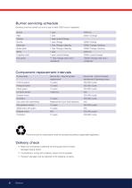
Servicing must be carried out once a year or after 3000 hours of operation Contactor 10 years 500,000 cycles The burner and its components must be recycled according to applicable regulations. Delivery check • Make sure everything is delivered and the goods have not been damaged during transit. • If something is wrong with a delivery, report it to the supplier. • Transport damage must be reported to the shipping company.
Open the catalog to page 6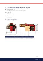
2. Technical data B 45i A 2,2H The burner is intended for: • Light oil, B10 heating oil/biofuel blend (as defined in DIN V51603-6) and is used for: • Water heating generators • Steam generators • Industrial applications • Hot air generators * Min. recommended distance to floor.
Open the catalog to page 7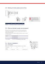
I*NB It is important that the spark does not strike M against the brake plate or nozzle 2.3 Recommended nozzle and pressure Because of the various boiler types with varying furnace geometries and furnace loads, it is impossible to commit to a certain scattering angle or a specific distribution pattern. It should be noted that the scattering angle and distribution pattern changes with pump pressure. 2.4 Burner installation 2.4.1 Hole patten Make sure the hole pattern on the boiler is designed for burner flange. Combustion device
Open the catalog to page 9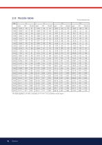
The table applies to oil with a viscosity of 4.4 mm 2/s at a density of 830 kg/m 3'
Open the catalog to page 10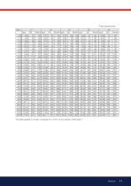
The table applies to oil with a viscosity of 4.4 mm 2/s at a density of 830 kg/m 3'
Open the catalog to page 11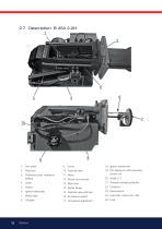
Test point Protective cover, Hydraulics Setting 19. AZL display for LMV automatic control unit 21. Thermal overload protection Ignition electrodes 15. Solenoid valve with bloc Brake plate 24. Automatic control unit LMV
Open the catalog to page 12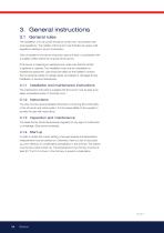
3. General instructions 3.1 General rules The installation of an oil burner should be carried out in accordance with local regulations. The installer of the burner must therefore be aware of all regulations relating to oil and combustion. Only oil suitable for the burner should be used and then in combination with a suitable oil filter before the oil pump of the burner. If the burner is replacing an existing burner make sure that the oil filter is replaced or cleaned. The installation must only be undertaken by experienced personnel. Care should be taken by the installer to ensure that no electrical...
Open the catalog to page 14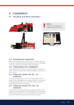
4. Installation 4.1 Handling and lifting instruktion Option The lifting aid we used here are available as spare parts, Figure 1. 4.2 Acceptance inspection Make sure everything is delivered and the goods have not been damaged during transit. If something is wrong with the delivery, report it to the supplier. Transport damage must be reported to the shipping company. 4.3 Preparations for installation Check that the burner’s dimensions and capacity range are suitable for the boiler in question. The power data on the type sign refers to the burner’s min. and max. power. 4.4 Pressure switch for min....
Open the catalog to page 15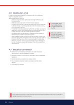
4.6 Distribution of oil In order to achieve good reliability, it is important that the oil distribution system is designed correctly. Take the following into account: - Selection of pipe diameter, pipe length and height difference; see Pump instruction. - Pipelines are to be laid with a minimal number of glands. - The pipes are to be laid so that the oil supply hoses are not subjected to tensile stresses or are excessively bent when the burner is swung out or removed for service. The oil filter must be installed before the burner’s oil pump. Be sure to fill the burner oil system before starting...
Open the catalog to page 16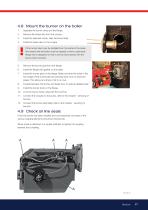
4.8 Mount the burner on the boiler 1. Separate the burner body and the flange. Remove the brake disc from the oil pipe. Install the selected nozzle. (See Technical data) Install the brake disc on the oil pipe If the burner tube must be installed from the inside of the boiler, this means that the boiler must be opened or have a spectacle flange that is designed so that it can be reconnected with the burner tube mounted. Remove the burner pipe from the flange. Install the flange with gasket on the boiler. Install the burner pipe on the flange. Make sure that the holes in the front edge of the burner...
Open the catalog to page 17All Bentone - Enertech AB catalogs and technical brochures
 Bentone B55
2 Pages
 Bentone B2 Classic
2 Pages
 Bentone B45-B55-B65
28 Pages
 Bentone B30-B40
24 Pages
 Fantastic History Amazing Future
12 Pages
 Bentone BG450 LN
48 Pages
 Bentone B65
2 Pages
 Bentone B45A
2 Pages
 Bentone B 45-2 MF
2 Pages
 Bentone B40A
2 Pages
 Bentone B30A
2 Pages
 Bentone B1 Classic
2 Pages
 Bentone B65-2 RME
2 Pages
 Bentone B70/B80
2 Pages
 Bentone BF1
2 Pages
 Bentone BF1 HC
2 Pages
 Bentone BF1 RME
2 Pages
 Bentone BF1-2
2 Pages
 Bentone BF1-2 HC
2 Pages
 Bentone BFG1
2 Pages
 Bentone BFG1 HC
2 Pages
 Bentone BFG1 LN
2 Pages
 Bentone BFG1-2
2 Pages
 Bentone BFG1-2 HC
2 Pages
 Bentone BG300/BG400
2 Pages
 Bentone BG450
2 Pages
 Bentone BG550/BG650
2 Pages
 Bentone BG700/BG800
2 Pages
 Bentone ST133/146
2 Pages
 Bentone STG 146
2 Pages
 Bentone BG950 500 - 3200 kW
2 Pages


