- Products
- Catalogs
- News & Trends
- Exhibitions
Tebevert III

Tebevert III
Catalog excerpts

W o r l d C l a s s P o w e r S o l u t i o n s TEBEVERT Switch-mode inverters
Open the catalog to page 1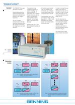
All monitoring and control units are designed to be intrinsically safe so that an uninterrupted supply of the connected load is ensured. These products have a very good dynamic range. At load peaks of 0 % – 100 % – 0 %, fluctuations and voltage surges are corrected within a very short time. In order to increase the availability of the system a mechanical by-pass can be provided. In case of inverter failure the system can be manually switched to mains supply (Fig. 2). The EUE (electronic bypass) is another component for increasing the system security. Using of the EUE loads are directly switched...
Open the catalog to page 2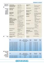
Typeseries Tebevert III Technical data: 1000 VA, 1500 VA, 2500 VA, 5000 VA, Type Type table Inverter with integrated mechanical by-pass Input DC voltage: see type table Permissible deviation: + 20 %, - 15 % Disconnection value: 1,7 V/C +/- 1V 2,4 V/C +/- 1 V Connection value: 2,05 to 2,1 V/C Ripple of the input voltage: max. 5 % rms. (2 mV reverse smoothing for 48 V and 60 V) Nominal power: see type table Output voltage: 230 V Efficiency: approx. 85 % Static deviation: +/- 5 % at total loading -, nominal voltage - and power factor range Frequency: 50 Hz Constance of frequency: +/- 0,1 % (at self-step)...
Open the catalog to page 3
Parallel operation of inverters Mechanical by-pass SUE Static bypass EUE Fig 6: Inverter with SUE Conventional inverter systems operate with a “passive redundancy” i.e. the mains does not supply the loads directly but will be connected in a fault situation. In contrast to this, parallel operating inverters, that are actively supplying the load (N or N+1 operation) offer an “active redundancy”. This operation mode requires a reliable exchange of information by the inverters via control signals. Furthermore a faulty unit has to be identified and switched off before the common busbar is affected....
Open the catalog to page 4
The control of parallel connected inverters ensures a uniform power distribution among the modules. The currents and bus voltage load of 1,11 kW is shown in fig. 7. Both are actively supplying the load. On failure of inverter A inverter B takes the full current load without a interference of the voltage. (Fig. 8). After fault clearance the inverter is connected parallel again. In Fig. 9 (see unit A) bringing the current on the inverter can be critical. The bus voltage is not affected. The Tebevert III inverter range can supply linear and non-linear loads. Fig. 10 shows currents at combinational...
Open the catalog to page 5
BENNING worldwide Austria Benning GmbH Elektrotechnik und Elektronik Eduard-Klinger-Str. 9 A-3423 St. Andrä-Wördern Tel. 0 22 42 / 3 24 16-0 Fax 0 22 42 / 3 24 23 E-Mail: [email protected] Belarus IOOO BENNING Belarus ul. Derzinskogo, 50 BY-224030, Brest Tel. 0162 / 22 07 21 Fax 0162 / 22 07 21 E-Mail: [email protected] Belgium Benning Belgium Power Electronics Z. 2 Essenestraat 16 B-1740 Ternat Tel. 02 / 58 287 85 Fax 02 / 58 287 69 E-Mail: [email protected] Croatia Benning Zagreb d.o.o. Trnjanska 61 HR-10000 Zagreb Tel. 1 / 61 97 060 Fax 1 / 61 97 059 E-Mail: [email protected] Czech Republic...
Open the catalog to page 6All Benning catalogs and technical brochures
 ENERTRONIC T
8 Pages
 UPS ENERTRONIC S
6 Pages
 INVERTRONIC modular
7 Pages
 INVERTRONIC compact
8 Pages
 DC-Converter 3000lDC
7 Pages
 Rectifier NPP
8 Pages
 TRANSOTRONIC
6 Pages
 Thyrotronic
8 Pages
 TEBECHOP 4000
2 Pages
 UPS ENERTRONIC L
8 Pages
 UPS ENERTRONIC I
8 Pages
 DC-Converters
4 Pages
 ADC modular
8 Pages
 Invertronic
8 Pages

- Rototherm DC power supply
- Rototherm AC/DC power supply
- Rototherm measuring instrument
- Single-output power supply
- Switching power supply
- Power supply for industrial applications
- Portable tester
- Battery charger
- Digital tester
- Rototherm tabletop power supply
- Rototherm compact power supply
- Automatic tester
- Industrial tester
- DIN rail power supply
- Digital gauge
- Portable gauge
- Multimeter
- Voltage testing system
- Digital multimeter