


Rectifier NPP

Rectifier NPP
Electronically controlled rectifier assemblies are utilized in nuclear power plants to provide a protected DC power supply system using lead-acid or nickel-cadmium batteries. These systems ensure continuous power supply to critical loads such as power station equipment, control electronics, telecommunications, and motors during both normal and failure conditions. The rectifiers offer output voltages of 110 V or 220 V and adhere to KTA guidelines.
The units operate with an IU charging characteristic as per DIN 41773, accommodating mains voltage variations of ±10%, frequency variations of ±5%, and load variations from 0 to 100%. The float charge voltage is set at 2.23 V per cell, with a boost charging voltage of 2.4 V per cell. During commissioning, the voltage can reach up to 2.7 V per cell.
Regulation is achieved through a controller with thyristors in a fully controlled three-phase bridge circuit. The units include reinforced smoothing devices to limit output voltage ripple to 5% peak-to-peak.
The power supply units are equipped with electronic monitoring modules integrated into a subrack. Key devices include:
- DÜW III: Monitors mains undervoltage, overvoltage, and balancing.
- GKÜ I: Monitors current-dependent undervoltage and system short circuits.
- GSR VII: Monitors dynamic and static overvoltage.
- GUG III: Monitors ripple content.
- SME I: Centralized fault indicator with first up value recording.
The rectifiers are housed in a welded steel section frame with IP 20 protection standards. The external construction includes a unit ON/OFF switch, ammeter, voltmeter, and fault indicators. Internally, the mains transformer and smoothing reactor are positioned at the base, with thyristor assemblies placed for optimal heat dissipation.
The rectifiers feature a fully controlled three-phase bridge circuit with transistorized controllers and thyristors. They are protected by ultra high-speed fuses and designed for natural air cooling. The units comply with EMV standards EN 50081-2 and EN 50082-2, and operate within an ambient temperature range of -5°C to +40°C.
Type tables provide detailed specifications for 24 V units, including mains current, power factor, efficiency, dissipated power, dimensions, and weights.
- 110 V Units: Models range from D 400 G 26/2000 to D 400 G 108/1600, with efficiencies between 87% to 94% and weights from 620 kg to 2400 kg.
- 220 V Units: Models range from D 400 G 212/100 to D 400 G 212/1200, with efficiencies between 93% to 97% and weights from 530 kg to 3200 kg.
Cabinets are specified with dimensions in height (H), width (W1 or W2), and depth (D), with variations for different models.
The battery supply units are designed as floor-standing sheet steel cabinets with features such as NH-fused load disconnection switch, battery circuit monitoring, ammeter, voltmeter, and copper bars for connections. They are available for 24 V, 110 V, and 220 V configurations.
The units include safety features to meet UVV BGV A2 requirements, ensuring protection against accidental contact. They are equipped with fuse monitoring, charging current measuring, and battery symmetry monitoring.
The document emphasizes the connection of the battery supply unit to the power supply via copper bus bars, with options for top or bottom cable entry. The units are marked with KKS for identification.
Catalog excerpts

Rectifiers For Stationary Battery Systems in Nuclear Power Plants
Open the catalog to page 1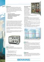
1.1 Application Electronically controlled rectifier assemblies are used in conjunction with suitable lead-acid or nickel-cadmium batteries, to provide a protected DC power supply system. These systems are then used to supply power to critical loads in nuclear power plants, both when the mains supply is present, and during power failures. Typical loads are: • Power station equipment • Signalling, control and protective electronics • Telemetering and telecontrol engineering • Telecommunications equipment • Static inverters • AC and DC motors • Solenoid valves The rectifier assemblies used normally...
Open the catalog to page 2
2. Signalling and Monitoring Devices The power supply units are fitted as standard with electronic monitoring modules. These are integrated into a subrack (Fig.3). If the voltage falls below 1.6 V per cell and the current is 100% of the nominal current, a fault signal is given. The signal is processed on the SME I and in the unit as described in 2.1. However the unit only switches itself back on once acknowledgement has been given on the SME I. 2.1 DÜW III Three-Phase Current Monitoring The DÜW III three-phase current monitoring device has three monitoring functions: • Mains undervoltage (VN...
Open the catalog to page 3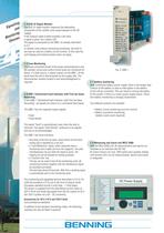
ling gnal d Si an ing nitor s Mo ice Dev 2.4 GUG III Ripple Monitor The GUG III ripple monitor measures the alternating component of the rectifier units superimposed on the DC voltage. If the residual ripple content exceeds a set value, a signal is given via a yellow LED. The signal is processed by the SME I as already described in 2.2. In rectifier units without reinforcing smoothing, the GUG III can also be used as a battery circuit monitor. In this case the unit tripping and locking function does not apply. 2.5 Fuse Monitoring The fuses connected ahead of the power semiconductors and the auxiliary...
Open the catalog to page 4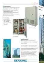
Cons truct ion of Rect ifier s 3.1 External Construction The units are built into a welded steel section framed housing to IP 20 protection standards and are designed with vents at the joints. The side and rear panels can be prepared. For transportation (loading and unloading) the housing is fitted with crane lifting eyes. If desired, casement-type or espagnolette fasteners can be used. At seismic requirements, additional mechanical reinforcements are implemented (see figure 6). The following display and control elements are positioned on the front door of the housing (see Fig. 5). • Unit ON/OFF...
Open the catalog to page 5
Charging characteristic: IU to DIN 41 773, can be switched to manually controlled W characteristic Operating modes: The mode required can be selected with a selector switch. Float charging: Parallel standby operation with IU characteristic, 2.23 V per cell Boost charging: Parallel standby operation with IU characteristic, 2.4 V per cell Commissioning charging: W characteristic at up to 2.7 V per cell. The charging current is smoothly adjustable. Stability of output values: Permitted variations under DIN 41 773: Mains voltage ± 10 % at 2.4 V/Z, + 10 - 15 % at 2.23 V/c Mains frequency variations...
Open the catalog to page 6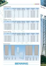
Power factor at 29 V and rated current Efficiency at 29 V and rated current Power factor at 121 V and rated current Efficiency at 121 V and rated current D 400 G 108/ 200 BWLrug-Dt D 400 G 108/ 300 BWLrug-Dt D 400 G 108/ 400 BWLrug-Dt D 400 G 108/ 600 BWLrug-Dt D 400 G 108/ 800 BWLrug-Dt D 400 G 108/1000 BWLrug-Dt D 400 G 108/1200 BWLrug-Dt D 400 G 108/1600 BWLrug-Dt Power factor at 245 V and rated current Efficiency at 245 V and rated current D 400 G 212/ 100 BWLrug-Dt D 400 G 212/ 200 BWLrug-Dt D 400 G 212/ 300 BWLrug-Dt D 400 G 212/ 400 BWLrug-Dt D 400 G 212/ 600 BWLrug-Dt D 400 G 212/ 800...
Open the catalog to page 7
ery Batt ly Supp s Unit General The battery supply unit connects the power supply to the battery, and is designed as a floor standing sheet steel cabinet, with hinged front door and corresponding KKS marking. The unit should stand adjacent to the power supply, and is connected via copper bus bar. The requirements of the UVV BGV A2 are met, especially with regard to protection against accidental contact. Equipment The standard battery supply units are equipped as follows: • NH-fused load disconnection switch equipped with the corresponding battery fuses with fuse monitoring. • battery circuit...
Open the catalog to page 8All Benning catalogs and technical brochures
 ENERTRONIC T
8 Pages
 UPS ENERTRONIC S
6 Pages
 INVERTRONIC modular
7 Pages
 INVERTRONIC compact
8 Pages
 DC-Converter 3000lDC
7 Pages
 TRANSOTRONIC
6 Pages
 Thyrotronic
8 Pages
 TEBECHOP 4000
2 Pages
 UPS ENERTRONIC L
8 Pages
 UPS ENERTRONIC I
8 Pages
 Tebevert III
6 Pages
 DC-Converters
4 Pages
 ADC modular
8 Pages
 Invertronic
8 Pages

- AC/DC power supply
- Measuring device
- Single-output power supply
- Portable tester
- Power supply for industrial applications
- Switched-mode power supply
- Battery charger
- Digital tester
- Compact power supply
- Automatic tester
- Industrial tester
- Tabletop power supply
- DIN rail power supply
- Digital gauge
- Voltage testing system
- Multimeter
- Portable gauge
- Benchtop tester