
- Catalogs
- BENEDIKT & JÄGER
- Circuit Breakers, Load Feeders

Circuit Breakers, Load Feeders

Circuit Breakers, Load Feeders
This document provides a comprehensive overview of the M4 series circuit breakers, focusing on their use for motor protection. It includes sections on specifications, technical data, accessories, installation, and dimensions.
The M4 circuit breakers come in various models, each with distinct rated currents and breaking capacities. Models such as M4-32T, M4-32R, M4-63R, and M4-100R are designed for different motor power ratings and short-circuit capacities.
This section details the rated ultimate short-circuit breaking capacity (Icu) and the rated service short-circuit breaking capacity (Ics) for various operational voltages. It also specifies when back-up fuses are necessary, especially if the short-circuit current exceeds the rated capacity.
A range of accessories is available, including auxiliary contacts, signalling switches, and auxiliary releases. The document provides details on operational current ratings, configurations, and mounting options for these accessories.
Includes insulated 3-pole busbar systems, terminal blocks, and DIN-rail adapters to ensure compatibility with standard mounting rails and contactors.
Detailed measurements for each circuit breaker model are provided to ensure proper fit and installation.
- Dimensions and technical data are subject to change without notice.
- Selecting the appropriate model and accessories is crucial based on the specific requirements of the electrical system and motor protection needs.
- Back-up fuses are recommended when the short-circuit current exceeds the circuit breaker's rated capacity.
1. Permissible Ambient Temperature: Storage/transport: -50 to +80°C, Operation: -20 to +60°C.
2. Rated Insulation Voltage: Ui V 690 for M4-32T and M4-32R, 1000 for M4-63R and M4-100R.
3. Rated Impulse Withstand Voltage: Uimp kV 6 for M4-32T and M4-32R, 8 for M4-63R and M4-100R.
4. Rated Operational Voltage: Ue V 690.
5. Rated Frequency: 50/60 Hz.
6. Utilization Category: IEC 60947-2 (circuit-breaker) A, IEC 60947-4-1 (motor starter) AC3.
7. Degree of Protection: IP 20.
8. Shock Resistance: 25g according to IEC 60068 Part 2-27.
9. Mechanical and Electrical Endurance: 100,000 cycles for M4-32T and M4-32R, 50,000 cycles for M4-63R and M4-100R.
Approved for use in USA, Canada, Switzerland, and Europe with certifications including UL and SEV.
1. Terminal Type: Pz2 for M4-32T, M4-32R, M4-63R; 4mm hexagon socket screw for M4-100R.
2. Tightening Torque: Varies from 0.8 to 6 Nm depending on the model.
3. Conductor Cross-Sections: Varies for solid, stranded, and flexible wires with specific AWG and mm² ranges.
1. M4 HQ..: Front transverse auxiliary switch with rated operational voltage Ue AC V 24 to 240.
2. M4 HS..: Lateral auxiliary switch with rated operational voltage Ue AC V 24 to 240.
1. Max. Short-Circuit Current: Varies by voltage level and model, with specific kA ratings.
2. Motor Load: Detailed HP ratings for 1-phase and 3-phase motors across different voltages.
1. Types: Rocker operating mechanism for M4-32T, rotary for others.
2. Locking: All mechanisms can be locked in the 0 position with a padlock.
1. Mounting: DIN-rail mounting with specific dimensions for each model.
2. Accessories: Various auxiliary contacts and releases available for installation.
Specific dimensions provided for each circuit breaker model, including height of arcing spaces and mounting details.
Catalog excerpts
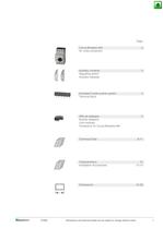
Page Circuit-Breakers M4 for motor protection 2 Auxiliary contacts Signalling switch Auxiliary releases 3 Insulated 3-pole busbar system Terminal block 4 DIN-rail adapters Busbar adapters Link modules Contactors for Circuit-Breakers M4 5 Technical Data 6-11 Characteristics Installation Accessories Dimensions D795E 12 13-14 15-20 Dimensions and technical datas are all subject to change without notice 1
Open the catalog to page 2
ReleasesCircuit-breakers M4 are equipped with bimetallic-based, inverse-time delayed overload releases and with instantaneous overcurrent releases(electromagnetic short-circuit releases). The overload releases can be set in accordance with the load current. The overcurrent releases are permanentlyset to a value 13 times the rated current and thus enable trouble-free start-up of motors. The scale cover can be sealed to prevent unauthorizedadjustments to the set current. Operating mechanismsCircuit-breakers M4-32T are actuated via a rocker operating mechanism and circuit-breakers M4-32R, M4-63R...
Open the catalog to page 12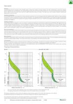
DIN-rail mountingOperating positions Current setting (dont rotate the dial out of the shown range)Connectioin of 1-phase motor > Circuit breaker > M4... Traverse Aux. Contact Block > M4 HQ11M4 HQ20M4HQ02 Aux. Contact Block (side mounted) > M4 HS11M4 HS20M4 HS02 Alarm Switch > M4 M11M4 MA11 Undervolatage Release > M4 U... Shunt Release > M4 A... D795EDimensions and technical datas are all subject to change without notice13 size="-1">
Open the catalog to page 13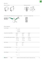
14Dimensions and technical datas are all subject to change without notice D795E >
Open the catalog to page 14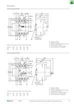
1)Side aux. contact2)Magnetic trip alarm 3)Shunt or undervoltage releaseHeight of arcing spaces (clearance from earthed parts )4)Transverse aux. contact5)Handle lock in OFF-position ( 5mm)at Ue (V)2404154605256906)35mm DIN-rail acc. to EN 50022 mm5050505050 inch22222 > 1)Side aux. contact 2)Magnetic trip alarm 3)Shunt or undervoltage releaseHeight of arcing spaces (clearance from earthed parts )4)Transverse aux. contact5)Handle lock in OFF-position (ؘ 5mm)at Ue (V)2404154605256906)35mm DIN-rail acc. to EN 50022 mm5070701101507)70mm DIN-rail acc. to EN 50023 inch2224,3368)4mm hexagon socket screw...
Open the catalog to page 16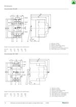
M4-32T + KG3-10. .M4-32T + KG3-14. .M4-32R + KG3-10. .M4-32R + KG3-14. . M4-32T + KG3-18. .M4-32T + KG3-22. .M4-32R + KG3-18. .M4-32R + KG3-22. . D795EDimensions and technical datas are all subject to change without notice17 >
Open the catalog to page 17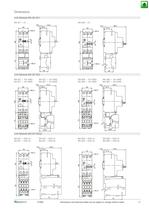
M4-32T + KG3-24 + M4 32 VDM4-32R + KG3-24 + M4 32 VD M4-32T + KG3-32 + M4 32 VDM4-32R + KG3-32 + M4 32 VD 18Dimensions and technical datas are all subject to change without notice D795E >
Open the catalog to page 18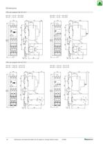
M4-63T + K3-50 + M4 63 VDM4-100R + K3-62 + M4 100 VD M4-63T + K3-62 + M4 63 VDM4-100R + K3-74 + M4 100 VD D795EDimensions and technical datas are all subject to change without notice19 >
Open the catalog to page 19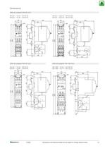
M4 32 S..M4 32 SE 20Dimensions and technical datas are all subject to change without notice D795E >
Open the catalog to page 20All BENEDIKT & JÄGER catalogs and technical brochures
 Key Switches M10 UP ..+SA
2 Pages
 General Catalogue
372 Pages
 Switches
97 Pages
 Contactors RAST 5
24 Pages
 Contactors Motor-Starters
126 Pages
 Modular Contactors and Switches
13 Pages
 Push Buttons
30 Pages
 Main Switches
21 Pages
 Manual Motor-Starters
6 Pages
 Capacitor Switching Contactors
13 Pages
 Short form Catalogue
30 Pages

