 Website:
BENDER
Catalog excerpts

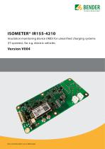
ISOMETER® Headline IR155-4210 Insulation monitoring device (IMD) for unearthed charging systems Sub-Headline (IT systems), for e.g. electric vehicles Vorläufiges Datenblatt
Open the catalog to page 1
Insulation monitoring device (IMD) for unearthed charging systems (IT systems), for e.g. electric vehicles Product description The ISOMETER® IR155-4210 monitors the insulation resistance between the insulated and active HV-conductors of an electrical drive/charger system (Un = DC 0…800 V) and the reference earth (chassis ground Kl.31). The patented measurement technology is used to monitor the condition of the insulation on the DC side as well as on the AC motor side of the electrical drive/charger system. Existing insulations faults will be signalised reliably even under high system...
Open the catalog to page 2
Wiring diagrams Connector XLB+ Pin 1+2 L+ Line voltage HV-System DC 0 V…1000 V (-420x only) HV-System DC 0 V…800 V (-4210 only) L- Connector XLBPin 1+2 L- Line voltage Connector XK1B Pin 1 Kl. 31 Chassis ground Pin 2 Kl. 15 Supply voltage Pin 3 Kl. 31 Chassis ground Pin 4 Kl. 31 Chassis ground (sep. line) Pin 5 MHS Data Out, PWM (high side) Pin 6 n.c. Pin 7 n.c. Pin 8 OKHS Status Output (high side) Notice: MHS only at -4204 and -4210 MLS only at -4203 Typical application Supply coupler Charger to vehicle diagnostic (load enable) Vehicle coupler LCharger relay Load enable relay Drive enable...
Open the catalog to page 3
Technical data Supply voltage Us DC 10…36 V Nominal supply voltage DC 12/24 V Voltage range 10…36 V 150 mA Max. operational current Is 2A Max. current Ik 6 A/2 ms Rush-In current <2 W Power dissipation Ps AC 0…800 V peak; Line L+/L- Voltage Un DC 0…1000 V UL 2231 DC 0…800 V Protective separation (reinforced insulation) between (L+/L-) – (Kl.31, Kl.15, E, KE, MHS, OKHS) Voltage test AC 3500 V/1 min Load dump protection < 40 V Under voltage detection 0…500 V; Default: 0 V (inactive) ≤ 1 µF System leakage capacity Ce > 1µF Reduced measuring range and increased measuring time at Ce (E.g. max....
Open the catalog to page 4
Operating principle PWM- driver • Condition “Normal” and “Under voltage detected” (10 Hz; 20 Hz) dcmeas = measured duty cycle (5…95 %) Crimp contacts Operating mode/mounting Temperature range Voltage dropout Fire protection class acc. UL94 Operating principle PWM- driver • Condition “SST” (30 Hz) Load current IL Turn-on time to 90 % VOUT Turn-off time to 10 % VOUT Slew rate on 10 to 30 % VOUT Slew rate off 70 to 40 % VOUT Timing 4210 Duty cycle 5…10 % (“Good”) 90 … 95 % (“Bad”) Operating principle PWM- driver • Condition “Device error” and “Kl.31 fault” (40 Hz; 50 Hz) Samtec Mini Mate...
Open the catalog to page 5
Ordering information Parameters Undervoltage detection Measured value output Continuously set value Customer-specific setting high-side high-side IR155-4210-200kΩ-100V + B91068143C The parameters acc. response value and under voltage detection have always to be added or included to an order. Dimension diagram Dimensions in mm 10mm copper circumferential on the rear side and 8.4mm on the front side Bender GmbH & Co. KG Londorfer Straße 65 • 35305 Grünberg • Germany Tel.: +49 6401 807-0 • info@bender.de • www.bender.de BENDER Group IR155-4210-V004_D00377_02_D_XXEN / 02.2022 / © Bender GmbH &...
Open the catalog to page 6All BENDER catalogs and technical brochures
-
ISOMETER® IR155-3210
6 Pages
-
CTBC17
2 Pages
-
CC612 EV charge controller
6 Pages
-
CC613 charge controller
6 Pages
-
Coupling device AGH150xx
4 Pages
-
IOM441-S / IOM441W-S
4 Pages
-
LINETRAXX® CTUB100-Serie
10 Pages
-
LINETRAXX® CTAC-Serie
6 Pages
-
ATICS®-...-DIO
6 Pages
-
COMTRAXX® COM465ID
8 Pages
-
COMTRAXX® COM465DP
8 Pages
-
COMTRAXX® COM465IP
8 Pages
-
COMTRAXX® CP9...-I Serie
6 Pages
-
POWERSCOUT®
8 Pages
-
LINETRAXX® CMD420/CMD421
6 Pages
-
LINETRAXX® VMD460-NA
8 Pages
-
LINETRAXX® VMD420
6 Pages
-
LINETRAXX® VME421H
6 Pages
-
LINETRAXX® VME420
6 Pages
-
Energy meter
6 Pages
-
NGRM700 (HRG)NGRM750 (LRG)
12 Pages
-
NGRM500 (HRG)NGRM550 (LRG)
10 Pages
-
RDC121
7 Pages
-
RCMB123
7 Pages
-
RCMB 121-2
7 Pages
-
RCMB121-1
7 Pages
-
LINETRAXX® MRCDB423
6 Pages
-
RDC104-4
6 Pages
-
LINETRAXX® RCMB330
4 Pages
-
LINETRAXX® RCMB300-Serie
12 Pages
-
Serie LINETRAXX® MRCDB300
12 Pages
-
LINETRAXX® RCMB42...
6 Pages
-
LINETRAXX® RCMS150 series
6 Pages
-
ISOSCAN® EDS440/441
12 Pages
-
ISOMETER® iso165C
6 Pages
-
ISOMETER® isoCHA425
6 Pages
-
ISOMETER® isoGEN423
6 Pages
-
ISOMETER® isoPV1685...
6 Pages
-
ISOMETER® isoMED427x-(PT)
6 Pages
-
ISOMETER® iso415R
4 Pages
-
ISOMETER® isoHR685W-x-I-B
10 Pages
-
ISOMETER® isoRW685W-D-B
8 Pages
-
ISOMETER® isoRW685W-D
8 Pages
-
ISOMETER® isoNAV685-D-B
8 Pages
-
ISOMETER® isoNAV685-D
8 Pages
-
ISOMETER® iso685-...-P
10 Pages
-
ISOMETER® iso685-...-B
8 Pages
-
ISOMETER® iso685
8 Pages
-
Isolated Power Systems Equipment
16 Pages
-
The Power in Electrical Safety
404 Pages
-
Coupling device AGH676S-4
4 Pages
-
Bender Remote Assist
8 Pages
-
300ST
4 Pages
-
400ST
4 Pages
-
UNIMET® 810ST
4 Pages
-
ISOSCAN® EDS460-DG
8 Pages
-
ISOSCAN® EDS460-D/EDS461-D
10 Pages
-
ISOMETER® IRDH575
8 Pages
-
ISOMETER® isoRW425
6 Pages
-
ISOMETER® IR123P
4 Pages
-
ISOMETER® IR423
6 Pages
-
ISOMETER® isoMED427P
6 Pages
-
ISOMETER® IR1575
6 Pages
-
ISOMETER® IR425-D4
6 Pages
-
ISOMETER® IR420-D4
6 Pages
-
TCP - Touch Control Panel
4 Pages
-
Series AT-Display panels
6 Pages
-
COMTRAXX® MK2430
6 Pages
-
ATICS®-…-DIO
4 Pages
-
ATICS®-…-ISO
6 Pages
-
UMA710-2-xx-ISO, ...-BP
44 Pages
-
USC710D4
6 Pages
-
Isolating transformer ES710
8 Pages
-
Isolating transformer DS0107
6 Pages
-
DI-1DL
4 Pages
-
DI-2
4 Pages


