- Catalogs
- BENDER GmbH & Co KG
- RCMB300-series
- Company
- Products
- Catalogs
- News & Trends
- Exhibitions
RCMB300-series
1 /12Pages
RCMB300-series
1 /12Pages
Catalog excerpts

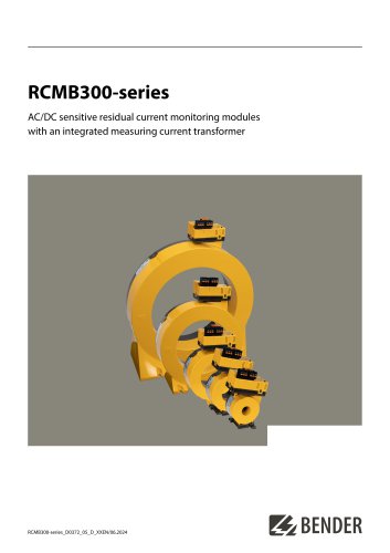
RCMB300-series AC/DC sensitive residual current monitoring modules with an integrated measuring current transformer
Open the catalog to page 1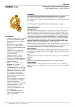
RCMB300-Series AC/DC sensitive residual current monitoring modules with an integrated measuring current transformer Device features • Continuous residual current monitoring in compliance with DGUV Vorschrift 3 (German Social Accident Insurance Regulation 3) • Easy DIN rail or screw mounting • RS-485 interface with Modbus RTU (reading out measured values/setting parameters) • Integrated switching outputs with two changeover contacts K1 and K2 (galvanically isolated) • Combined test and reset button • Multicolour LED indicating operation, exceeded response value, disturbances and status messages...
Open the catalog to page 2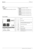
Variants Electronic modules Type B modular residual current module acc. to IEC 60755 Measuring current transformers (P = shielded) Measuring current transformer, internal diameter 20 mm Measuring current transformer, internal diameter 35 mm Measuring current transformer, internal diameter 60 mm Measuring current transformer, internal diameter 120 mm Measuring current transformer, internal diameter 210 mm
Open the catalog to page 3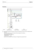
Wiring diagram 21, 22, 24 = Relay for main alarm = surge protection device The use of a type 2 surge protection device (SPD) is mandatory due to possible impulse voltages and in order to comply with normative requirements. The surge protection device must be connected upstream of the power supply unit on the supply side. Features of the surge protection device: – Nominal discharge current In (8/20 μs): 20 kA – Response time: 25 ns – Two-stage: 1 varistor + 1 spark gab Alternatively, the power supply unit must be connected to a CAT II supply without a surge protection device.
Open the catalog to page 4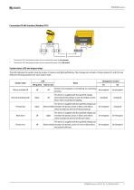
EBENDERConnection RS-485 interface (Modbus RTU) The internal The internal The LED indicates the system state by means of colours and lighting/flashing. The changeover contacts of relay outputs K1 and K2 have defined switching positions for each system state.
Open the catalog to page 5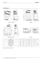
Dimension diagrams
Open the catalog to page 6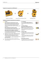
Example for the composition of an RCMB module Measuring current transformer: CTBC35 Final RCMB module Installation instructions for measuring current transformers CAUTION Device damage due to high induction currents! High currents can be induced into the conductor loop due to the AC/DC sensitive measurement technology used. Do not route protective conductors and lowresistance conductor loops through the measuring current transformer! Device damage due to interference pulses! The connecting cable (supply, analogue interface…) must not be routed directly past the current transformer core. Risk...
Open the catalog to page 8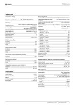
Technical data ( )* = factory setting Measuring circuit Insulation coordination acc. to IEC 60664-1/IEC 60664-3 Internal diameter measuring current see "Dimension diagrams", Page 6 Definitions Characteristics according to IEC 62020 AC/DC sensitive, type B Control circuit 1 (IC3) Control circuit 2 (IC4) Rated insulation voltage Overvoltage category Pollution degree Operating altitude Primary conductors routed through the current transformer Terminal block 1 (24 V, GND, T/R, GND, A, B, X1, X2) Terminal block 2 (11, 12, 14) Terminal block 3 (21,22, 24) 800 V Ml 2 Response value /4n Prewarning 30...
Open the catalog to page 9
Multicolour LED red/green, Refer to "System states: LED and output relays", Page 5 Required terminals are included in the scope of delivery. Phoenix Contact The connection conditions of the manufacturer apply. Maximum length connecting cable 10 m Connection properties with ferrules Number of changeover contacts Relay mode Switching capacity Contact data acc. to IEC 60947-5-1 Rated operational voltage AC Utilisation category Rated operational current AC Rated operational current AC (for UL applications) Rated operational voltage DC Utilisation category Rated operational current DC Minimum current...
Open the catalog to page 10
RBENDER Ordering details Measuring current transformers Accessories
Open the catalog to page 11
Bender GmbH & Co. KG Londorfer Straße 65 35305 Grünberg Germany Tel.: +49 6401 807-0 [email protected] www.bender.de © Bender GmbH & Co. KG, Germany Subject to change! The specified standards take into account the edition valid until 06.2024 unless otherwise indicated.
Open the catalog to page 12All BENDER GmbH & Co KG catalogs and technical brochures
 CD25000
4 Pages
 CD14400
4 Pages
 CD1000
4 Pages
 AUR381Z
4 Pages
 AN110
AN1104 Pages
 AGH575S-6
4 Pages
 CD1000-2
4 Pages
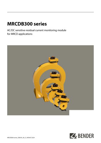 MRCDB300 series
12 Pages
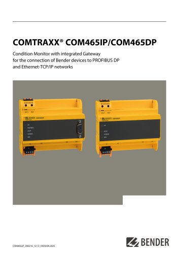 COMTRAXX® COM465IP/COM465DP
10 Pages
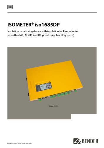 ISOMETER® iso1685DP
10 Pages
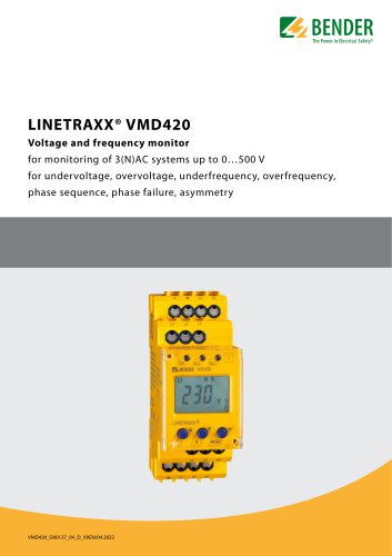 LINETRAXX® VMD420
6 Pages
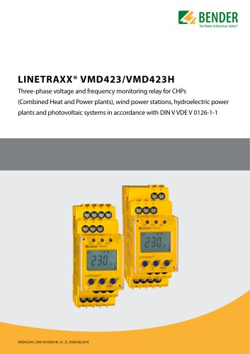 LINETRAXX® VMD423/VMD423H
6 Pages
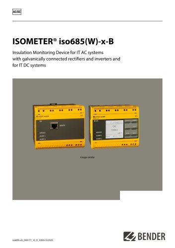
 ISOMETER® iso685(W)-x-B
12 Pages
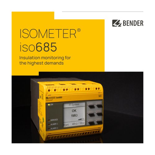 ISOMETER® iso685
12 Pages
 UNIMET® 810ST
4 Pages
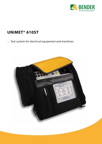 UNIMET® 610ST
4 Pages
 UNIMET® 400ST
4 Pages
 UNIMET® 300ST
4 Pages
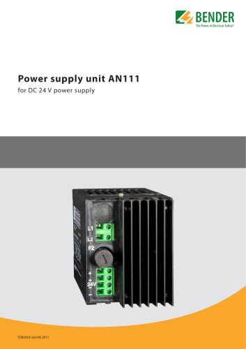 AN111
AN1114 Pages
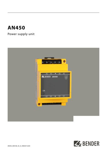 AN450
AN4504 Pages
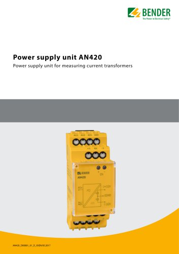 AN420
AN4204 Pages
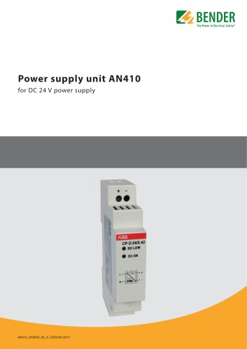 AN410
AN4104 Pages
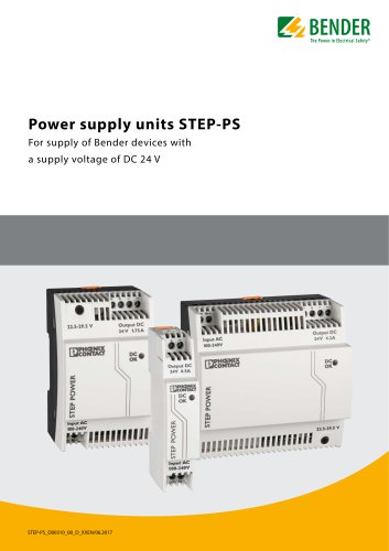 STEP-PS
8 Pages
 CTBC17 series
8 Pages
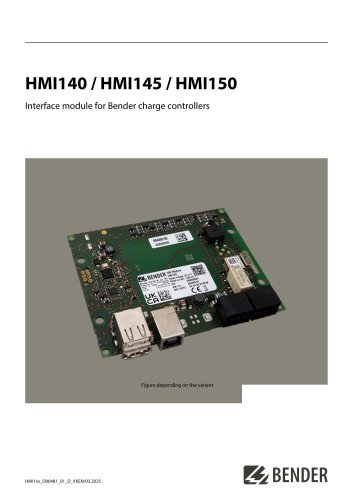 HMI140 / HMI145 / HMI150
6 Pages
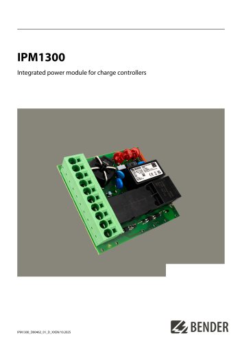 IPM1300
8 Pages
 CC613
CC6136 Pages
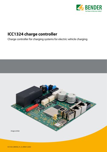 ICC1324
8 Pages
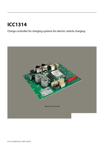 ICC1314
8 Pages
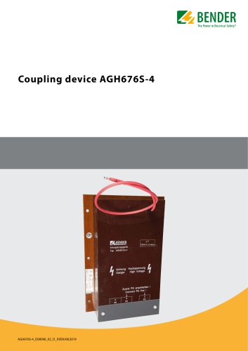 AGH676S-4
4 Pages
 AGH520S
4 Pages
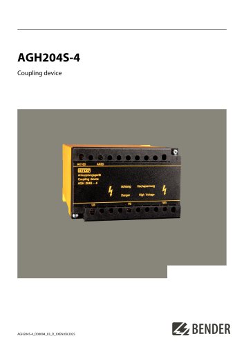 AGH204S-4
4 Pages
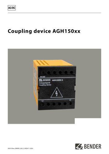 AGH150xx
4 Pages
 LINETRAXX® WF… series
4 Pages
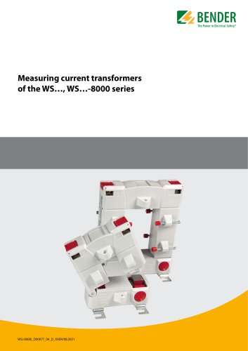 WS…, WS…-8000 series
4 Pages
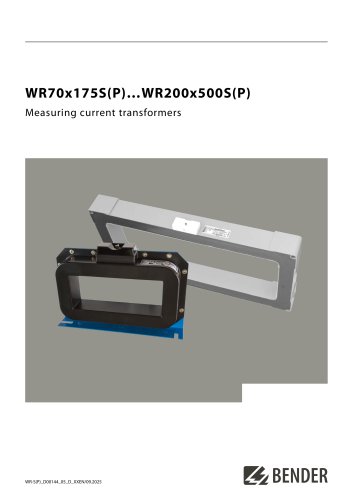 WR70x175S(P)…WR200x500S(P)
4 Pages
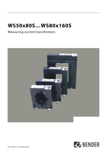 WS50x80S…WS80x160S
4 Pages
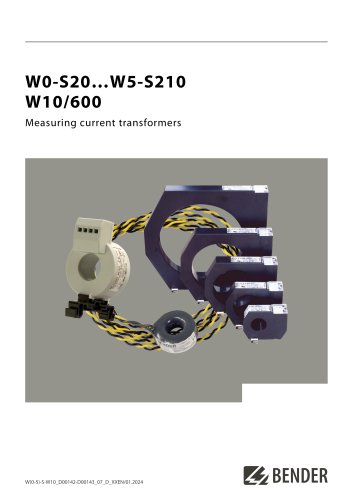 W0-S20…W5-S210 W10/600
4 Pages
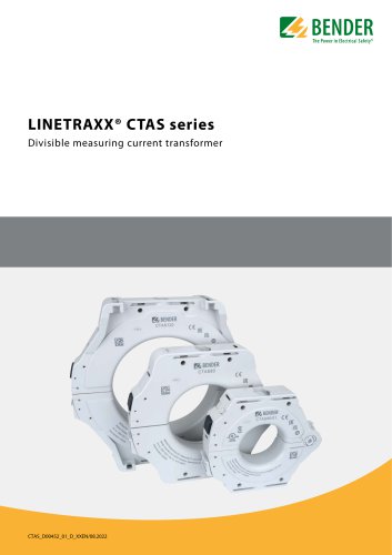 LINETRAXX® CTAS series
8 Pages
 LINETRAXX® CTBS25
4 Pages
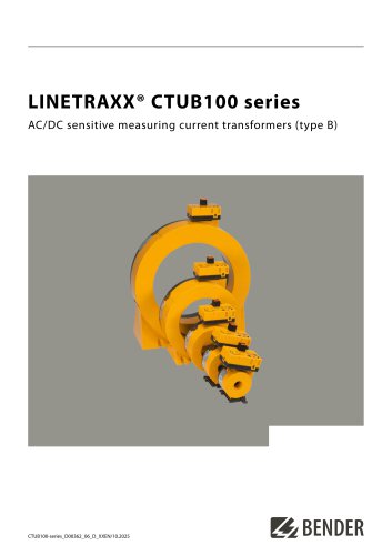 LINETRAXX® CTUB100 series
10 Pages
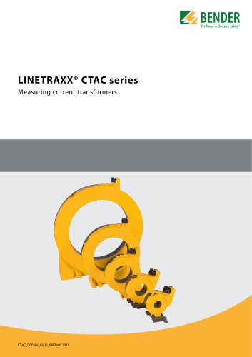 LINETRAXX® CTAC series
6 Pages
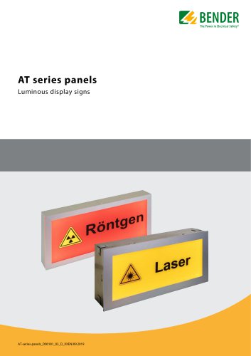 AT series
6 Pages
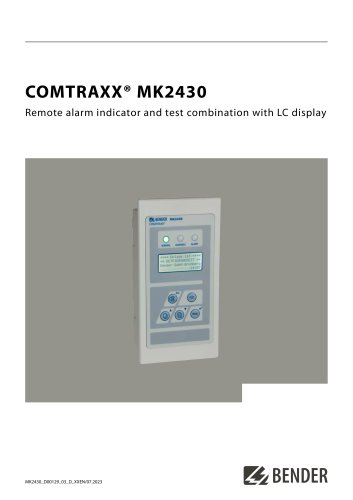 COMTRAXX® MK2430
6 Pages
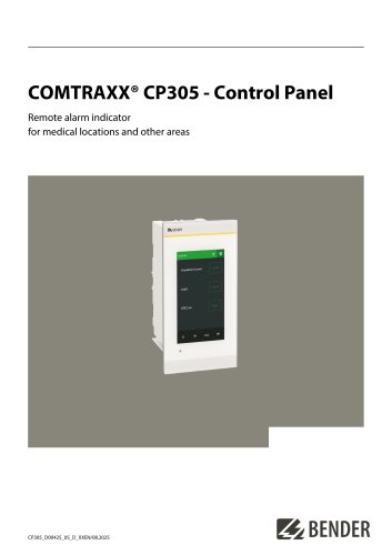 COMTRAXX® CP305
12 Pages
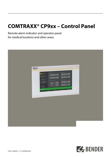 COMTRAXX® CP9xx
8 Pages
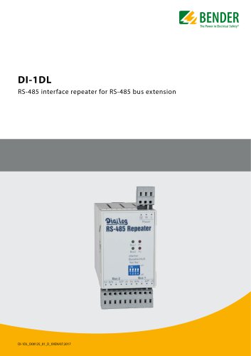 DI-1DL
4 Pages
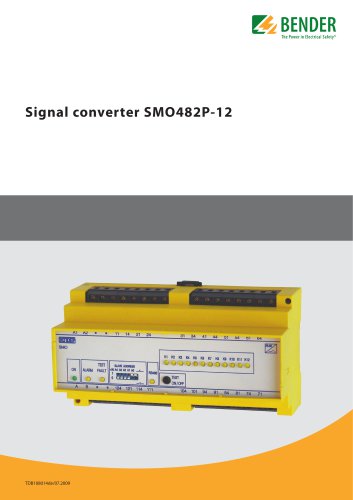 SMO482P-12
4 Pages
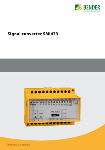 Signal converter SMI473
4 Pages
 DI-2USB
4 Pages
 COMTRAXX® COM463BC
7 Pages
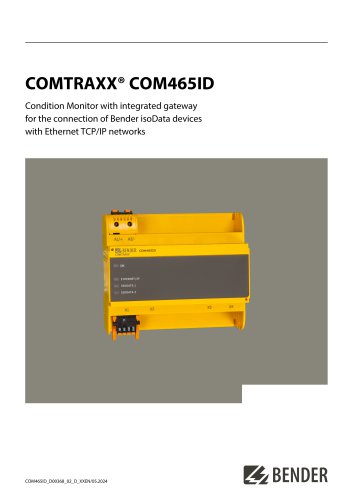 COMTRAXX® COM465ID
8 Pages
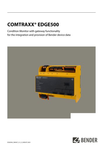 COMTRAXX® EDGE500
12 Pages
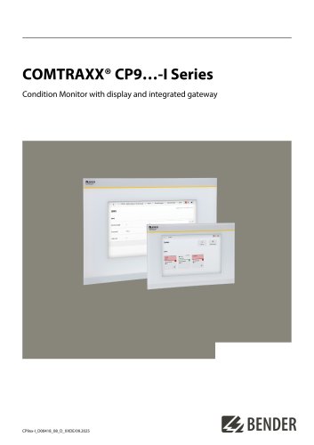 COMTRAXX® CP9…-I Series
10 Pages
 POWERSCOUT®
8 Pages
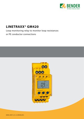 LINETRAXX® GM420
6 Pages
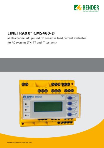 LINETRAXX® CMS460-D
10 Pages
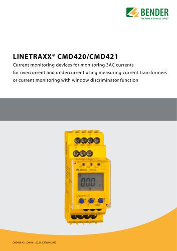 LINETRAXX® CMD420/CMD421
6 Pages
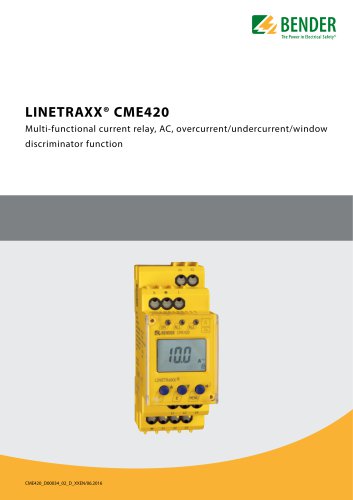 LINETRAXX® CME420
6 Pages
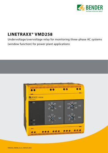 LINETRAXX® VMD258
6 Pages
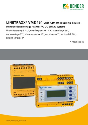 LINETRAXX® VMD461
10 Pages
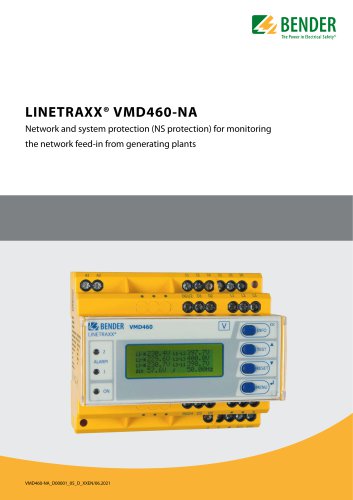 LINETRAXX® VMD460-NA
8 Pages
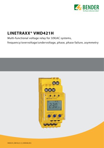 LINETRAXX® VMD421H
6 Pages
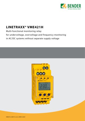 LINETRAXX® VME421H
6 Pages
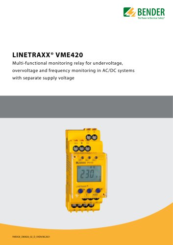 LINETRAXX® VME420
6 Pages
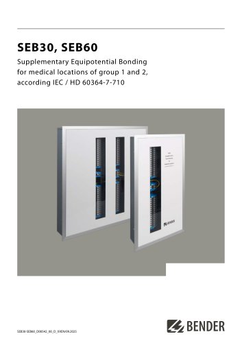 SEB30, SEB60
8 Pages
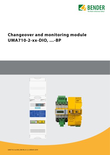 UMA710-2-xx-DIO, …-BP
6 Pages
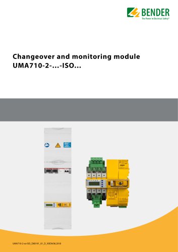 UMA710-2-…-ISO…
6 Pages
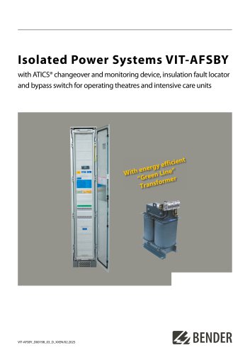 VIT-AFSBY
6 Pages
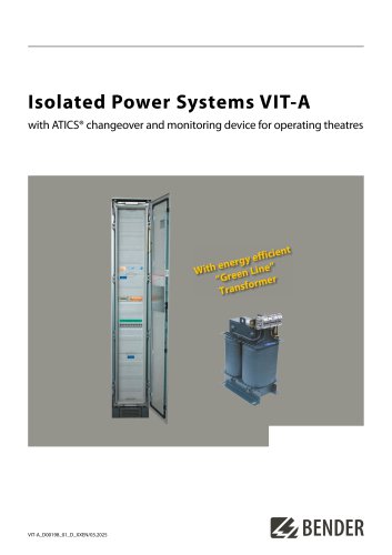 VIT-A
VIT-A6 Pages
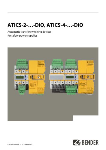 ATICS-2-…-DIO, ATICS-4-…-DIO
8 Pages
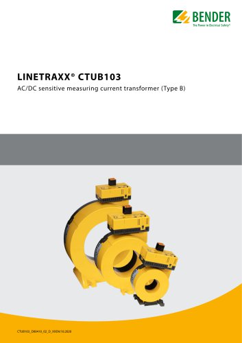 LINETRAXX® CTUB103
6 Pages
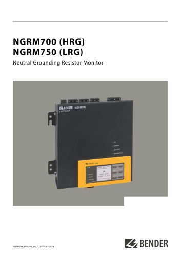 NGRM700 (HRG)/NGRM750 (LRG)
12 Pages
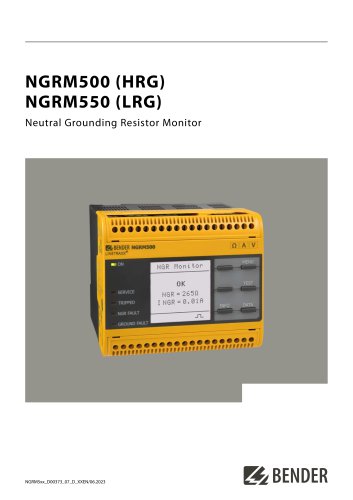
 NGRM500 (HRG)/NGRM550 (LRG)
12 Pages
 RDC125-5S
12 Pages
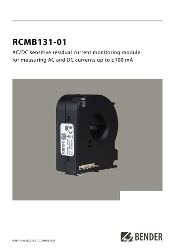 RCMB131-01
4 Pages
 RDC121
7 Pages
 RCMB123
7 Pages
 Residual current sensors
2 Pages
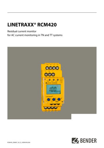 LINETRAXX® RCM420
6 Pages
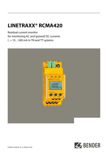 LINETRAXX® RCMA420
6 Pages
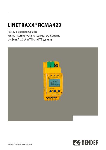 LINETRAXX® RCMA423
6 Pages
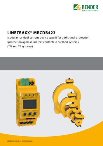 LINETRAXX® MRCDB423
6 Pages
 RDC104-4
6 Pages
 RCMB104
6 Pages
 LINETRAXX® RCMB330
4 Pages
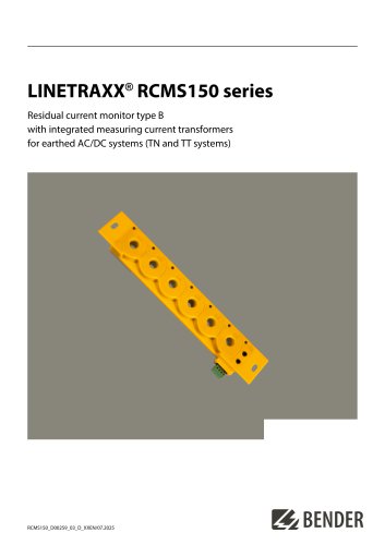 LINETRAXX® RCMS150 series
8 Pages
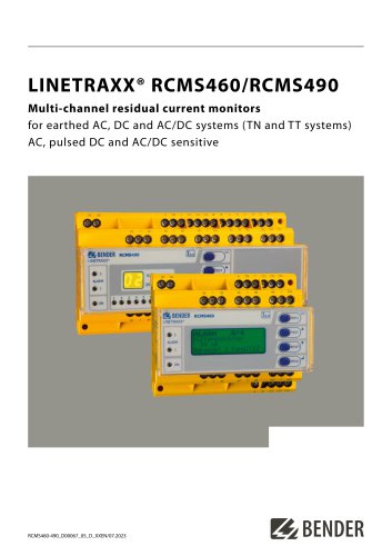 LINETRAXX® RCMS460/RCMS490
14 Pages
 LINETRAXX® SmartDetect RCMS410
10 Pages
 IOM441-S / IOM441W-S
4 Pages
 EDS3090/-91/-92/-96
14 Pages
 ISOSCAN® EDS150/151
6 Pages
 ISOSCAN® EDS440/EDS441
16 Pages
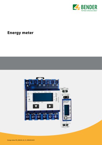 Energy meter
6 Pages
 PEM353
8 Pages
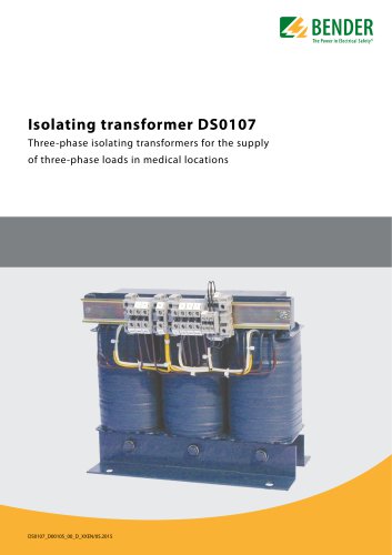 DS0107
6 Pages
 ESL0107
4 Pages
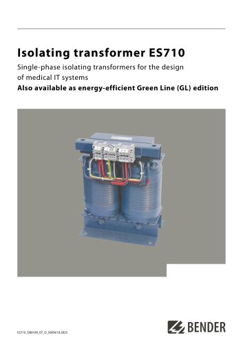 ES710
ES7108 Pages
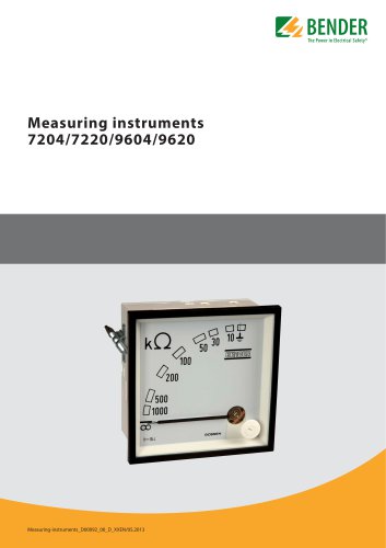 7204/7220/9604/9620
4 Pages
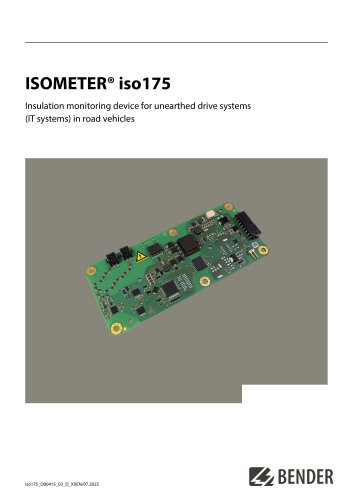 ISOMETER® iso175
8 Pages
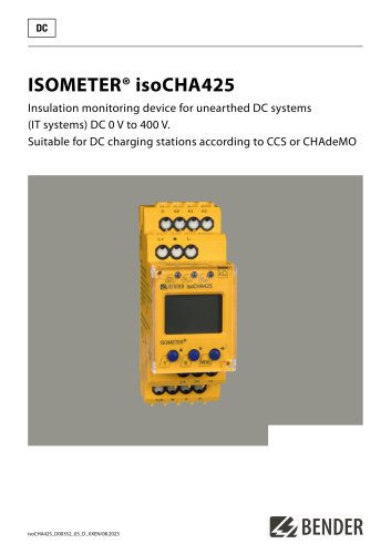 ISOMETER® isoCHA425
8 Pages
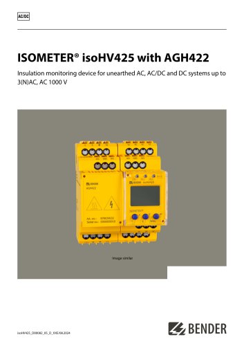 ISOMETER® isoHV425 with AGH422
10 Pages
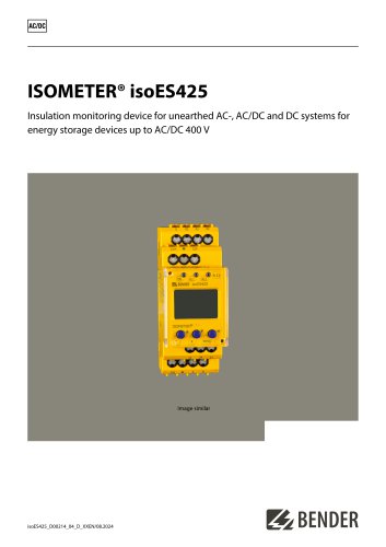 ISOMETER® isoES425
8 Pages
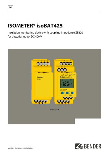 ISOMETER® isoBAT425
8 Pages
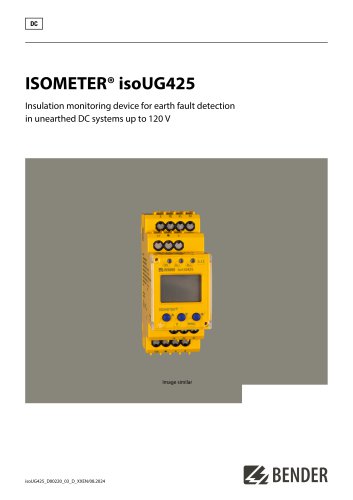 ISOMETER® isoUG425
6 Pages
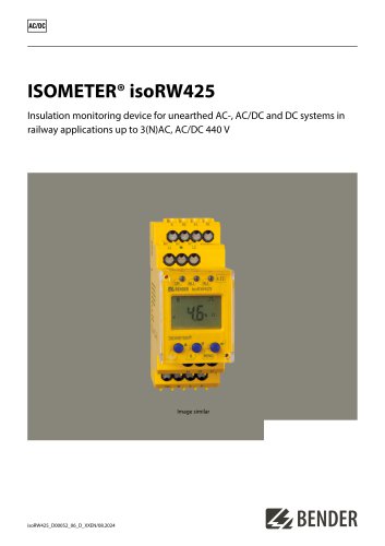 ISOMETER® isoRW425
8 Pages
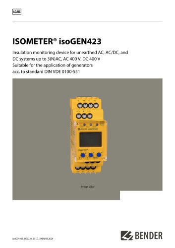 ISOMETER® isoGEN423
6 Pages
 ISOMETER® IR123P
4 Pages
 ISOMETER® IR423
6 Pages
 ISOMETER® IR420-D6
6 Pages
 ISOMETER® isoPV1685DP
10 Pages
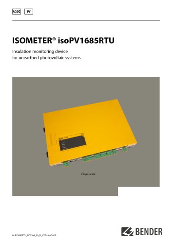 ISOMETER® isoPV1685RTU
8 Pages
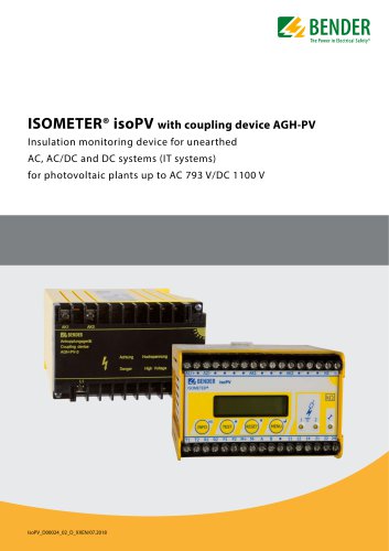 ISOMETER® isoPV
8 Pages
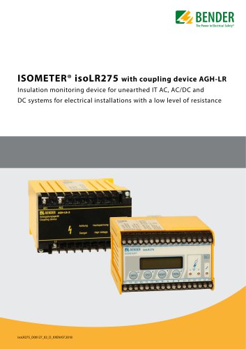 ISOMETER® isoLR275
6 Pages
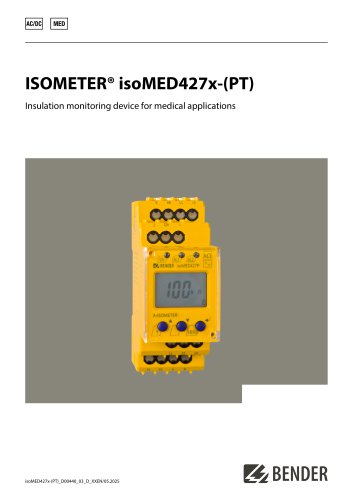 ISOMETER® isoMED427x-(PT)
6 Pages
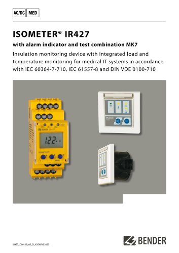 ISOMETER® IR427
8 Pages
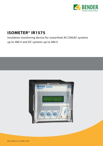 ISOMETER® IR1575
6 Pages
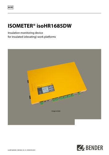 ISOMETER® isoHR1685DW
10 Pages
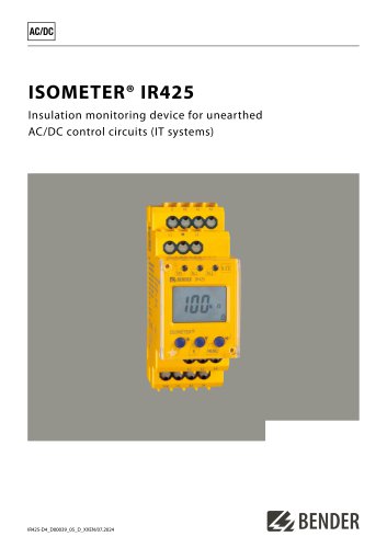 ISOMETER® IR425-D4
6 Pages
 ISOMETER® IR420-D4
6 Pages
 ISOMETER® iso415R
2 Pages
 ISOMETER® IRDH275BM-7
6 Pages
 ISOMETER® isoRW685W-D-B
10 Pages
 ISOMETER® isoRW685W-D
10 Pages
 ISOMETER® isoHR685W-x-I-B
10 Pages
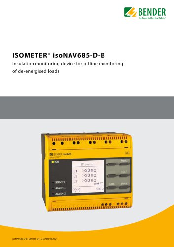 ISOMETER® isoNAV685-D-B
8 Pages
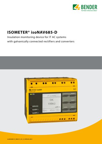 ISOMETER® isoNAV685-D
8 Pages
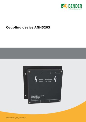 AGH520S
4 Pages
 NGRM500 et NGRM550
12 Pages
 RCM410R
8 Pages
 RCMS410
10 Pages
 RCMS425-D
10 Pages
 EDGE500
12 Pages
 Iso415R
4 Pages
 Iso685-x-B
12 Pages
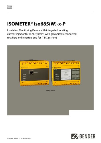 Iso685-x-P
14 Pages
 Iso685-x
12 Pages
 Data Centers
16 Pages
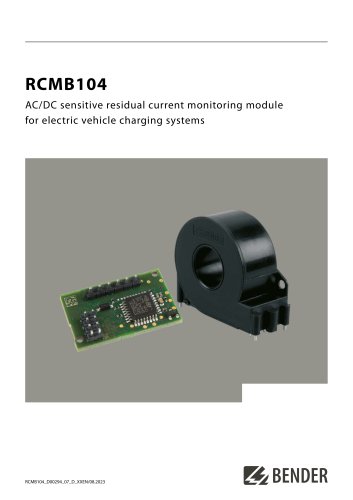 RCMB104
6 Pages
 LINETRAXX® RCMS460 / RCMS490
14 Pages
 LINETRAXX® SmartDetect RCMS410
10 Pages
 Main Catalogue
486 Pages


- DC power supply
- Display module
- AC/DC power supply
- Measuring device
- BENDER dry transformer
- CE power supply
- Cloud-based software
- Single-output power supply
- Power supply for industrial applications
- Portable tester
- Monitoring software solution
- Communication gateway
- LED display panel
- BENDER IEC transformer
- Power supply with overload protection
- Compact power supply