
- Catalogs
- BENDER GmbH & Co KG
- RCM410R


- Company
- Products
- Catalogs
- News & Trends
- Exhibitions
RCM410R
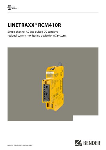
RCM410R
The LINETRAXX® RCM410R is a single-channel residual current monitoring device designed for AC systems, sensitive to both AC and pulsed DC currents. It complies with DIN EN IEC 62020-1, Type A standards, and is suitable for preventive maintenance in TN, TT, and IT systems.
Key Features
- RMS measurement with a residual operating current range of 10 mA to 30 A.
- Prewarning capability at 50-100% of the residual operating current.
- Supply voltage options: DC 24 V or AC/DC 100-240 V (RCM410R-2).
- LED-strip for measured value display and adjustable response delay.
- Alarm relay with selectable N/C or N/O operation and fault memory behavior.
- RS-485 with Modbus RTU and NFC interface for parameter setting.
Intended Use
The RCM410R is intended for use with specified measuring current transformers for monitoring residual currents in AC systems. It is designed for installation in control cabinets or protected environments.
Functional Description
Upon applying supply voltage, the device undergoes a start-up delay. Residual current detection is performed via an external current transformer. Alarms are triggered if the measured value exceeds set thresholds, with options for prewarning and main alarms.
Technical Specifications
- Insulation coordination: Rated voltage of 250 V, overvoltage category III.
- Supply voltage: DC 24 V or AC/DC 100-240 V with specific tolerances.
- Measuring circuit: Frequency range of 42-70 Hz, with a measuring range of 2 mA to 70 A peak.
- Time response: Configurable start-up delay, response delay, and release delay.
- RS-485 interface: Modbus RTU protocol with a maximum baud rate of 115.2 kbits/s.
Environmental and Mechanical Conditions
- Operating temperature: -25 to +55 °C.
- Protection degree: IP20 for terminals, IP30 for internal components.
- Mounting: Vertical on DIN rail.
Approvals and Standards
The device complies with standards such as DIN EN IEC 62020-1, UL508, and UL1053. It also meets the requirements of the Radio Equipment Directive 2014/53/EU.
Ordering Information
Available in two models: RCM410R-24 (DC 24 V) and RCM410R-2 (DC 24 V, AC/DC 100-240 V). Accessories include a sealable transparent cover.
Catalog excerpts
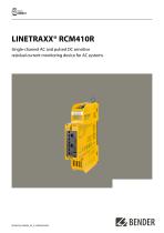
LINETRAXX® RCM410R Single-channel AC and pulsed DC sensitive residual current monitoring device for AC systems
Open the catalog to page 1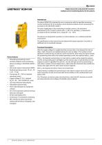
LINETRAXX® RCM410R Single-channel AC and pulsed DC sensitive residual current monitoring device for AC systems Device features • Alternating and pulsing current sensitive residual current monitoring device according to DIN EN IEC 62020-1, Type A • Root mean square measurement (RMS) • Residual operating current: 10 mA...30 A (42...70 Hz) • Prewarning: 50.100 % of residual operating current • Supply voltage DC 24 V , optional AC/DC 100.240 V (RCM410R-2 only) • LED-strip measured value display • Adjustable response delay • Alarm relay (designed as changeover contact) • N/C or N/O operation and fault...
Open the catalog to page 2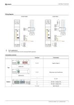
Wiring diagrams J For UL applications: The current transformers must be connected before operation. Measuring current transformer
Open the catalog to page 3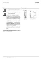
Dimension diagrams The NFC interface can be used to transmit a previously configured device parameter setting directly to the device. This function is available only via the Bender Connect App. You can find this app in the Appstores for iOS and Android. In the Bender Connect app the device first needs to be made known. Then the device-specific setting options are shown so that they can be configured. When the data is transferred, feedback is given whether the parameter configuration has been successful. Parameter settings can be transmitted to the device via the Bender Connect app by holding...
Open the catalog to page 4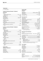
Technical data Measuring & control circuit (IC1) S1, S2, +, -, A, B Operating altitude < 2000 m AMSL Rated impulse voltage Rated insulation voltage Protective separation (reinforced insulation) between Voltage test (routine test) acc. to IEC 61010-1 Measuring & control circuit (IC3) S1, S2, +, -, A, B Operating altitude < 2000 m AMSL Rated impulse voltage Rated insulation voltage Protective separation (reinforced insulation) between Voltage test (routine test) acc. to IEC 61010-1 Connection Supply voltage Us Tolerance of US Power consumption Inrush current (< 5 ms) Connection Supply voltage Us...
Open the catalog to page 5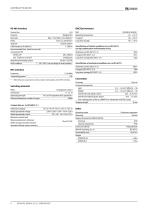
Modbus RTU Max. 115.2 kbits/s (19.2 kbits/s)* even, no, odd (even)* 1/2/auto (auto)* <1200m Connection Protocol Baud rate Parity Stop bits Cable length (at 9.6 kbits/s) Recommended lines, shield on one side connected to PE min. J-Y(St)Y 2 x 0.6 mm2 Twisted pair Required terminating resistor 120 0 (> 0.25 W) Device address 1...247 (100 + last two digits of serial number)* ** EMC influences may lead to communication interruptions at the NFC interface. Switching elements Operating principle Electrical endurance, number of cycles Operating temperature Transport Long-time storage Classification of...
Open the catalog to page 6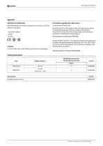
ApprovalsStandards & certifications The RCM410R device has been developed in accordance with the following standards: For a list of the open-source software used see our Homepage. Bender GmbH & Co. KG hereby declares that the device covered by the Radio Equipment Directive complies with Directive 2014/53/EU. The full text of the EU Declaration of Conformity is available at the following internet address: Hereby, Bender GmbH & Co. KG declares that this radio equipment complies with Radio Equipment Regulations 2017 (S.I. 2017/1206). The full text of the UK declaration of conformity is available...
Open the catalog to page 7
Bender GmbH & Co. KG Londorfer Straße 65 35305 Grünberg Germany Tel.: +49 6401 807-0 [email protected] www.bender.de © Bender GmbH & Co. KG, Germany Subject to change! The specified standards take into account the edition valid until 08.2025 unless otherwise indicated.
Open the catalog to page 8All BENDER GmbH & Co KG catalogs and technical brochures
 CD25000
4 Pages
 CD14400
4 Pages
 CD1000
4 Pages
 AUR381Z
4 Pages
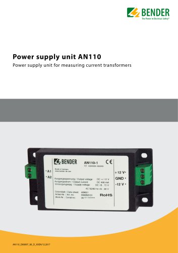 AN110
AN1104 Pages
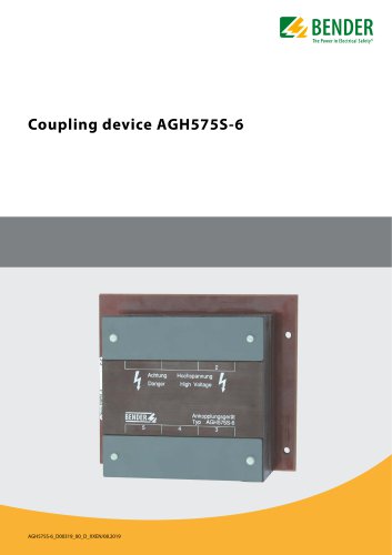 AGH575S-6
4 Pages
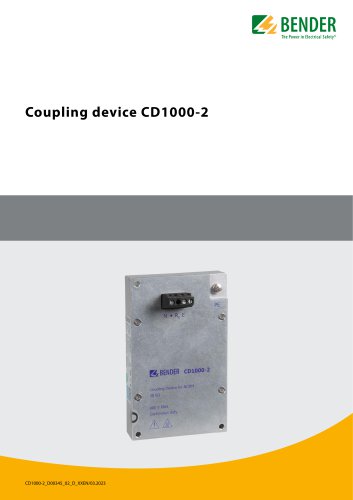 CD1000-2
4 Pages
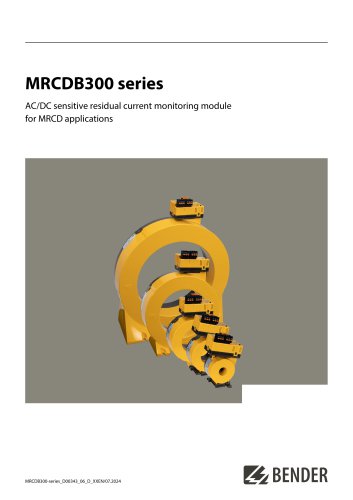 MRCDB300 series
12 Pages
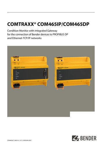 COMTRAXX® COM465IP/COM465DP
10 Pages
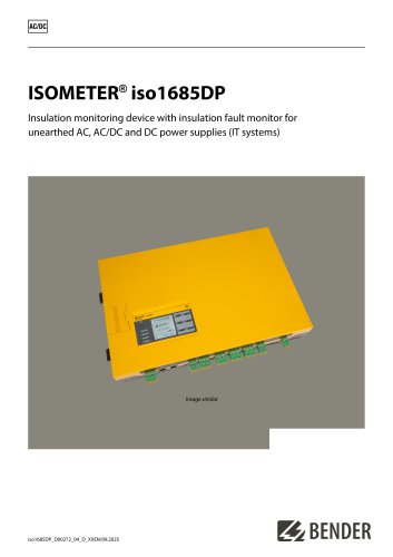 ISOMETER® iso1685DP
10 Pages
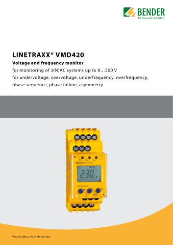 LINETRAXX® VMD420
6 Pages
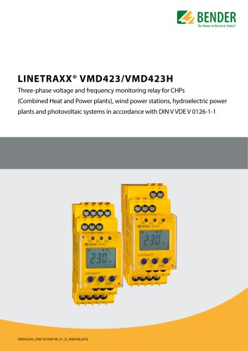 LINETRAXX® VMD423/VMD423H
6 Pages
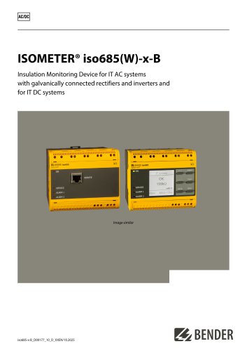 ISOMETER® iso685(W)-x-B
12 Pages
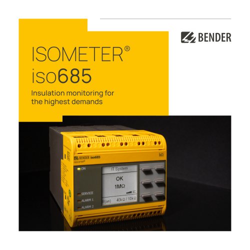 ISOMETER® iso685
12 Pages
 UNIMET® 810ST
4 Pages
 UNIMET® 610ST
4 Pages
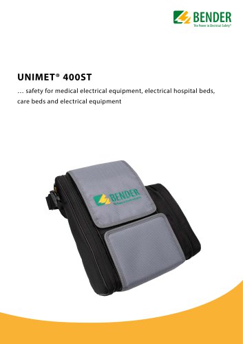 UNIMET® 400ST
4 Pages
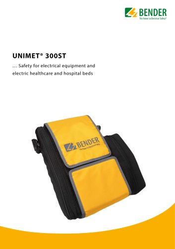 UNIMET® 300ST
4 Pages
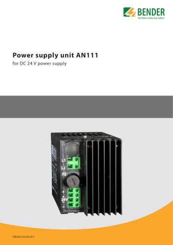 AN111
AN1114 Pages
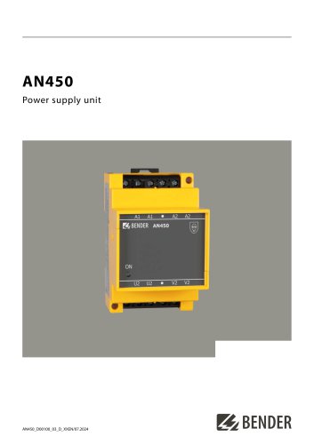 AN450
AN4504 Pages
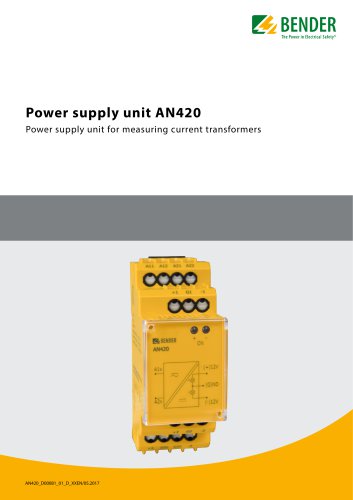 AN420
AN4204 Pages
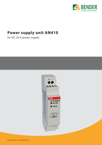 AN410
AN4104 Pages
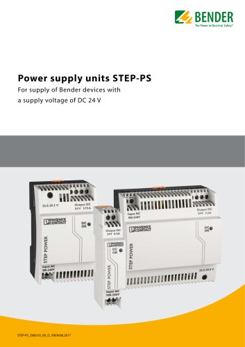 STEP-PS
8 Pages
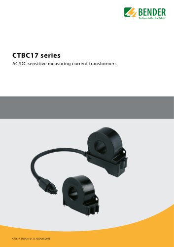 CTBC17 series
8 Pages
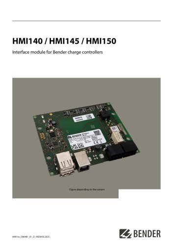 HMI140 / HMI145 / HMI150
6 Pages
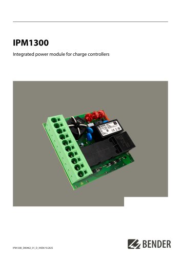 IPM1300
8 Pages
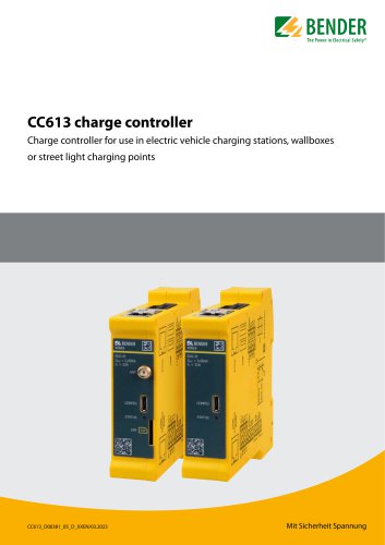 CC613
CC6136 Pages
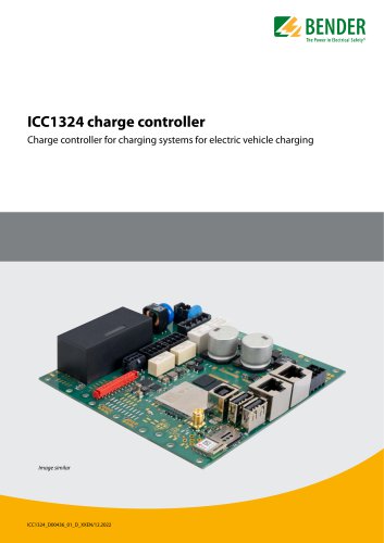 ICC1324
8 Pages
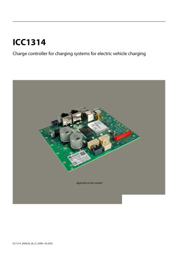 ICC1314
8 Pages
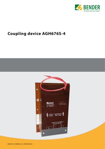 AGH676S-4
4 Pages
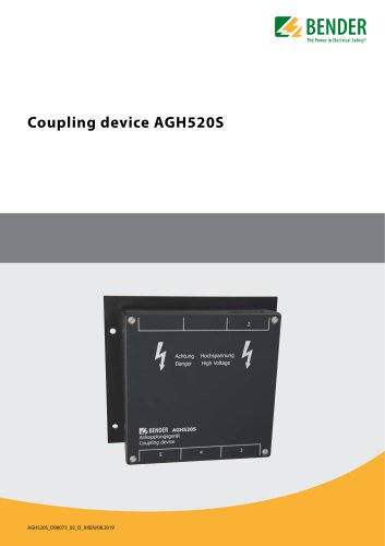 AGH520S
4 Pages
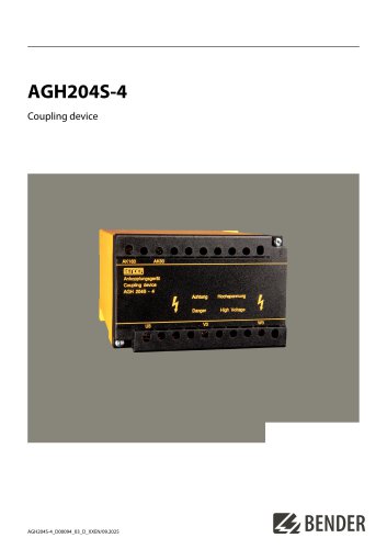 AGH204S-4
4 Pages
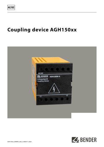 AGH150xx
4 Pages
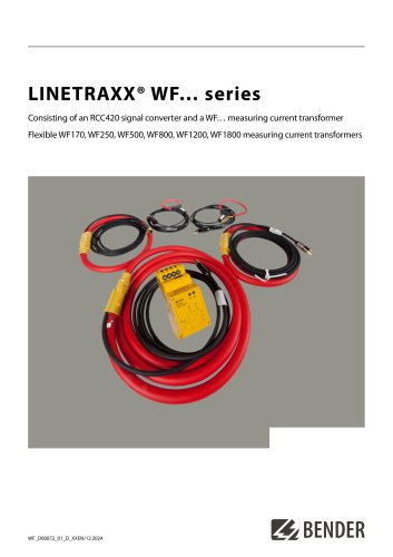 LINETRAXX® WF… series
4 Pages
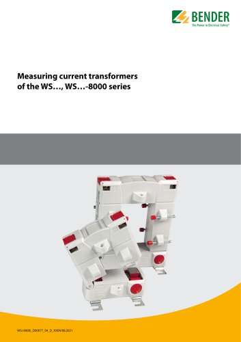 WS…, WS…-8000 series
4 Pages
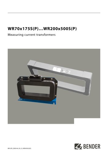 WR70x175S(P)…WR200x500S(P)
4 Pages
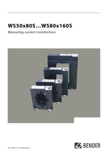 WS50x80S…WS80x160S
4 Pages
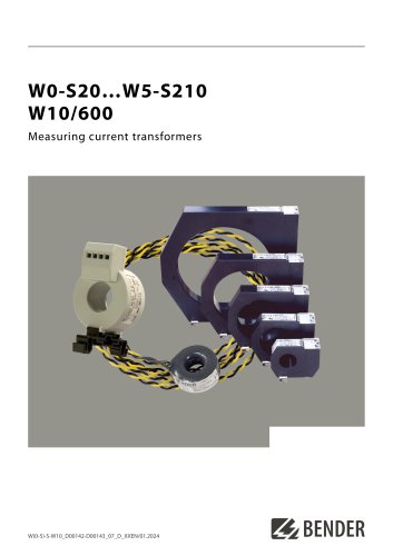 W0-S20…W5-S210 W10/600
4 Pages
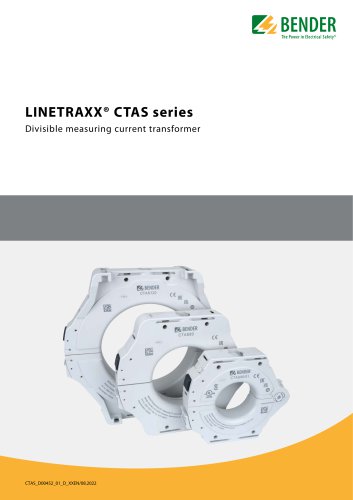 LINETRAXX® CTAS series
8 Pages
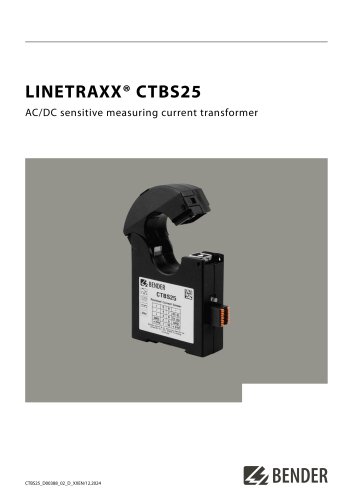 LINETRAXX® CTBS25
4 Pages
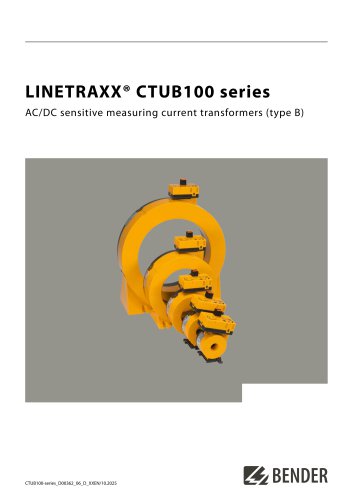 LINETRAXX® CTUB100 series
10 Pages
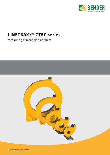 LINETRAXX® CTAC series
6 Pages
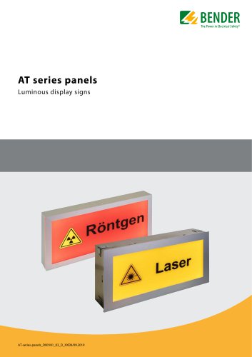 AT series
6 Pages
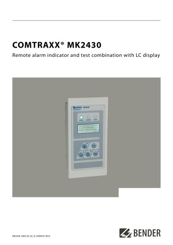 COMTRAXX® MK2430
6 Pages
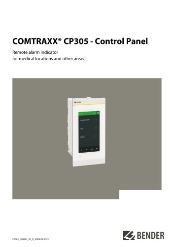 COMTRAXX® CP305
12 Pages
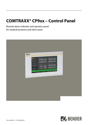 COMTRAXX® CP9xx
8 Pages
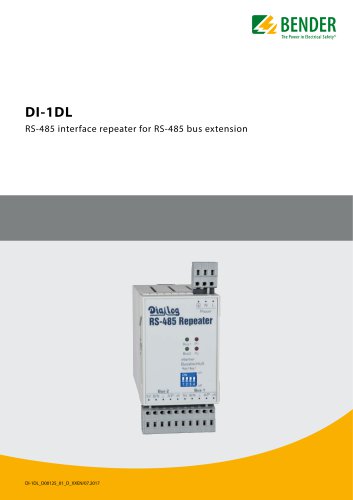 DI-1DL
4 Pages
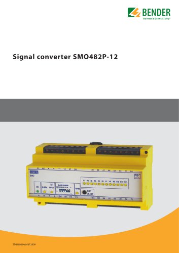 SMO482P-12
4 Pages
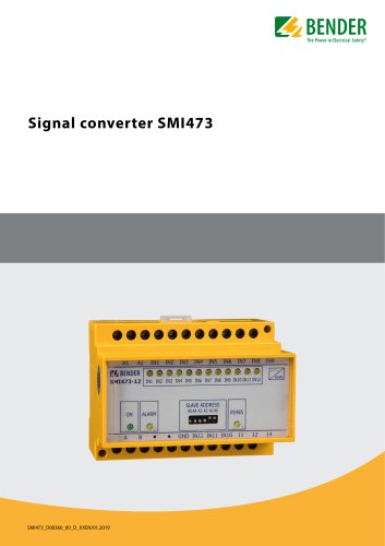 Signal converter SMI473
4 Pages
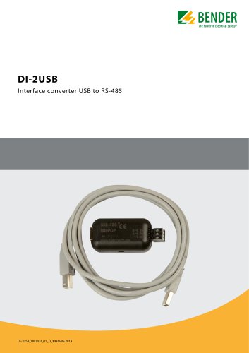 DI-2USB
4 Pages
 COMTRAXX® COM463BC
7 Pages
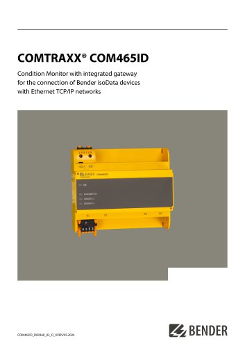 COMTRAXX® COM465ID
8 Pages
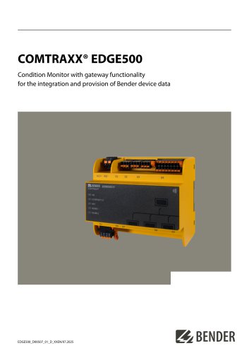 COMTRAXX® EDGE500
12 Pages
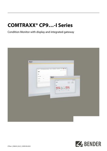 COMTRAXX® CP9…-I Series
10 Pages
 POWERSCOUT®
8 Pages
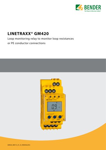 LINETRAXX® GM420
6 Pages
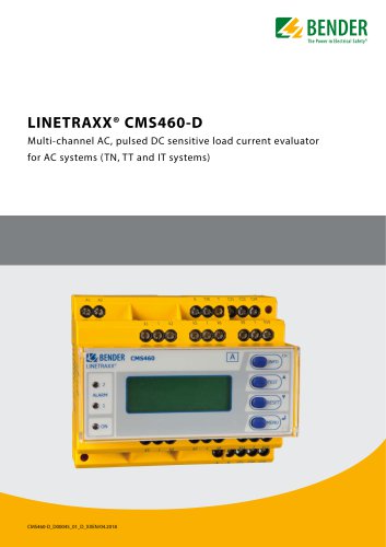 LINETRAXX® CMS460-D
10 Pages
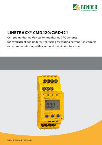 LINETRAXX® CMD420/CMD421
6 Pages
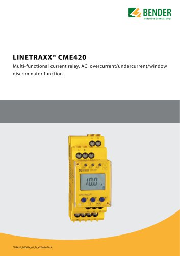 LINETRAXX® CME420
6 Pages
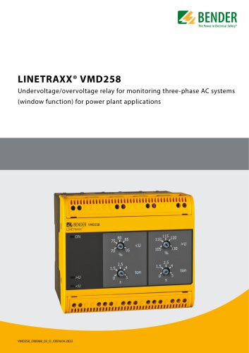 LINETRAXX® VMD258
6 Pages
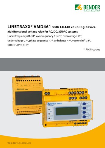 LINETRAXX® VMD461
10 Pages
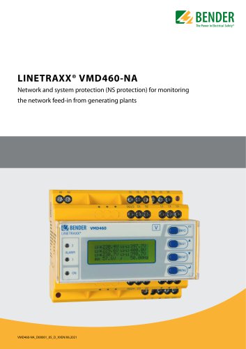 LINETRAXX® VMD460-NA
8 Pages
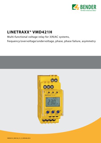 LINETRAXX® VMD421H
6 Pages
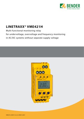 LINETRAXX® VME421H
6 Pages
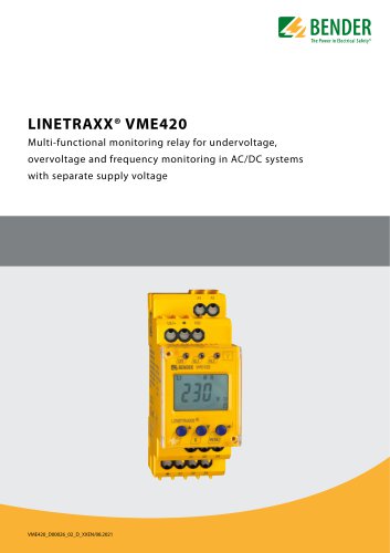 LINETRAXX® VME420
6 Pages
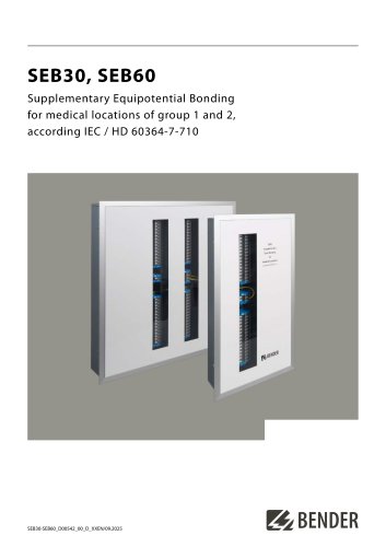 SEB30, SEB60
8 Pages
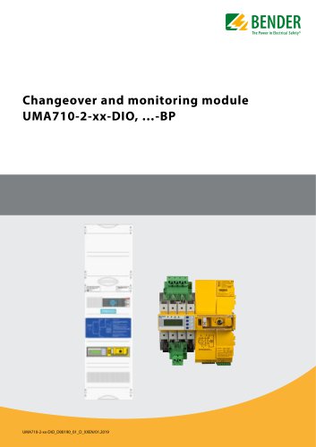 UMA710-2-xx-DIO, …-BP
6 Pages
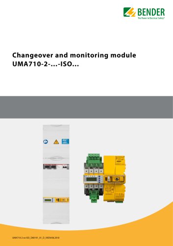 UMA710-2-…-ISO…
6 Pages
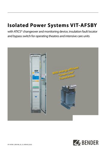 VIT-AFSBY
6 Pages
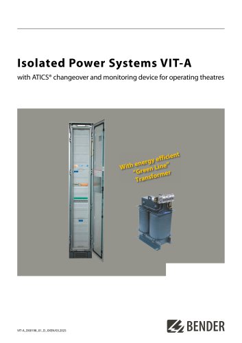 VIT-A
VIT-A6 Pages
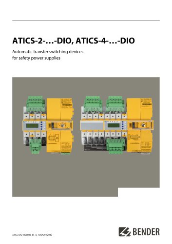 ATICS-2-…-DIO, ATICS-4-…-DIO
8 Pages
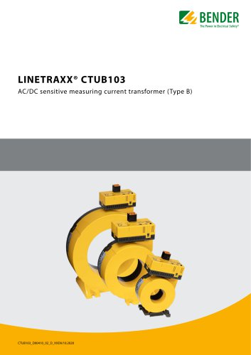 LINETRAXX® CTUB103
6 Pages
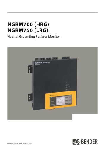 NGRM700 (HRG)/NGRM750 (LRG)
12 Pages
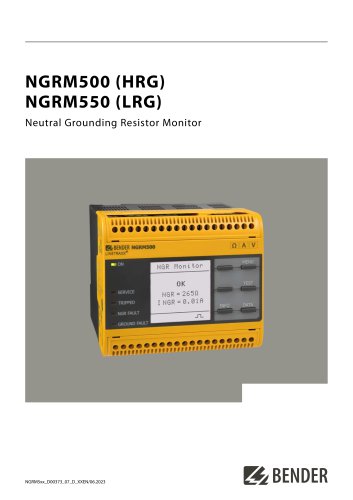 NGRM500 (HRG)/NGRM550 (LRG)
12 Pages
 RDC125-5S
12 Pages
 RCMB131-01
4 Pages
 RDC121
7 Pages
 RCMB123
7 Pages
 Residual current sensors
2 Pages
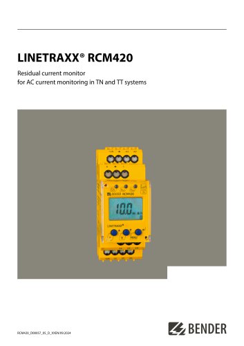 LINETRAXX® RCM420
6 Pages
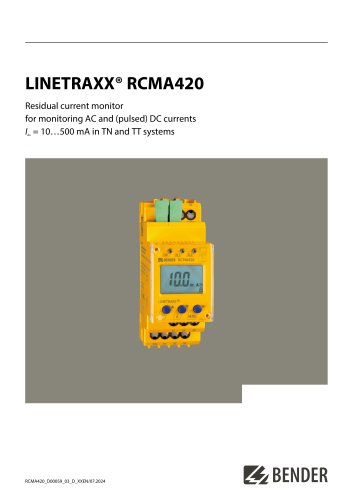 LINETRAXX® RCMA420
6 Pages
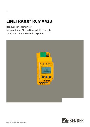 LINETRAXX® RCMA423
6 Pages
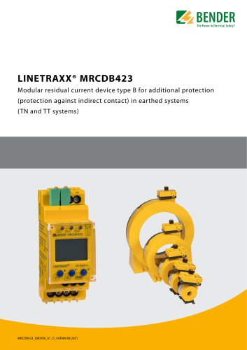 LINETRAXX® MRCDB423
6 Pages
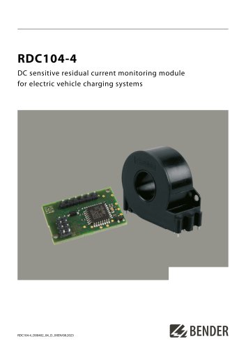 RDC104-4
6 Pages
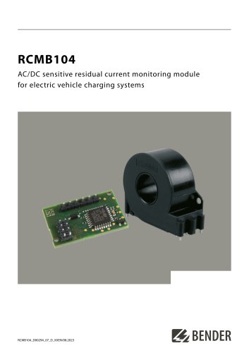 RCMB104
6 Pages
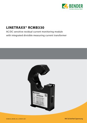 LINETRAXX® RCMB330
4 Pages
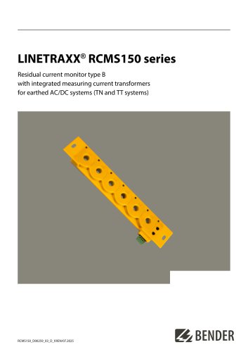 LINETRAXX® RCMS150 series
8 Pages
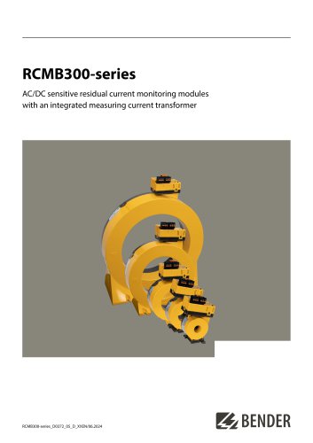 RCMB300-series
12 Pages
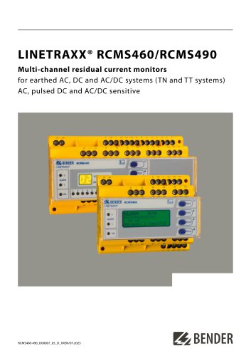 LINETRAXX® RCMS460/RCMS490
14 Pages
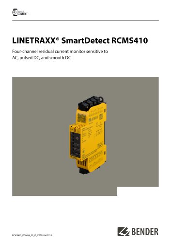 LINETRAXX® SmartDetect RCMS410
10 Pages
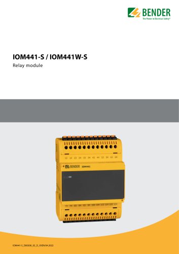 IOM441-S / IOM441W-S
4 Pages
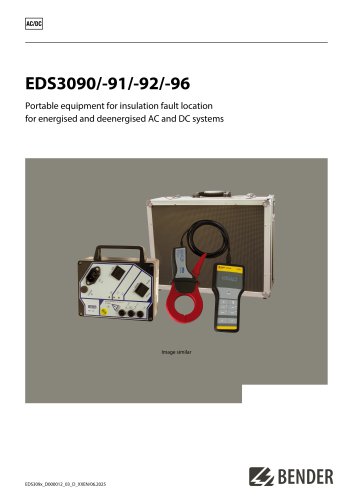 EDS3090/-91/-92/-96
14 Pages
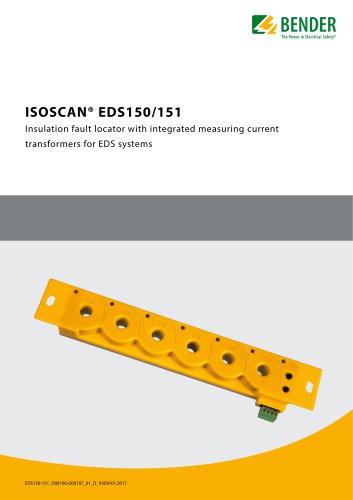 ISOSCAN® EDS150/151
6 Pages
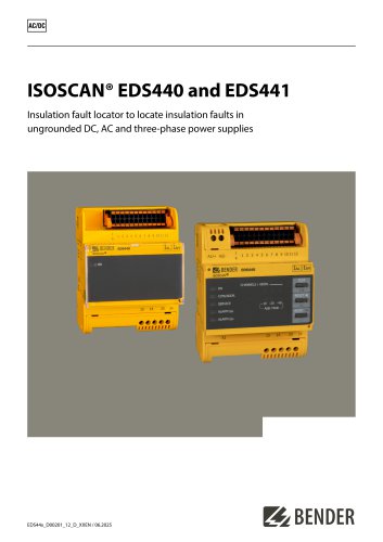 ISOSCAN® EDS440/EDS441
16 Pages
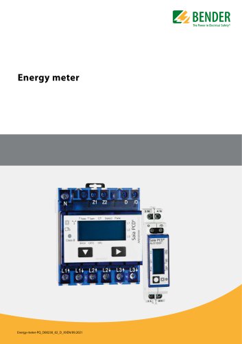 Energy meter
6 Pages
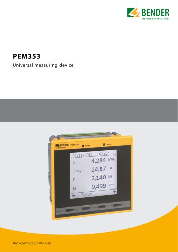 PEM353
8 Pages
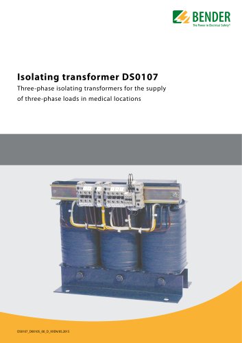 DS0107
6 Pages
 ESL0107
4 Pages
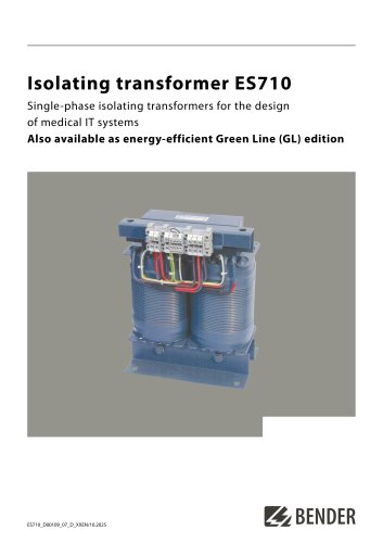 ES710
ES7108 Pages
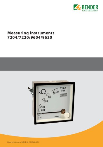 7204/7220/9604/9620
4 Pages
 ISOMETER® iso175
8 Pages
 ISOMETER® isoCHA425
8 Pages
 ISOMETER® isoHV425 with AGH422
10 Pages
 ISOMETER® isoES425
8 Pages
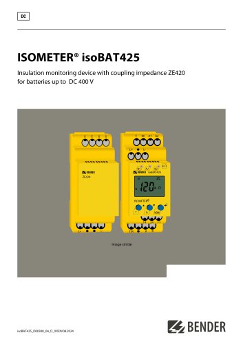 ISOMETER® isoBAT425
8 Pages
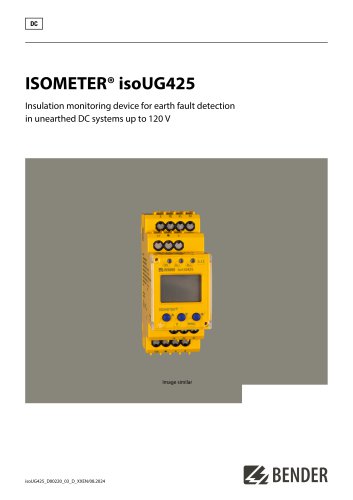 ISOMETER® isoUG425
6 Pages
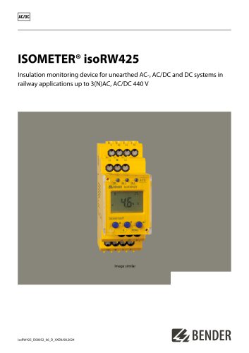 ISOMETER® isoRW425
8 Pages
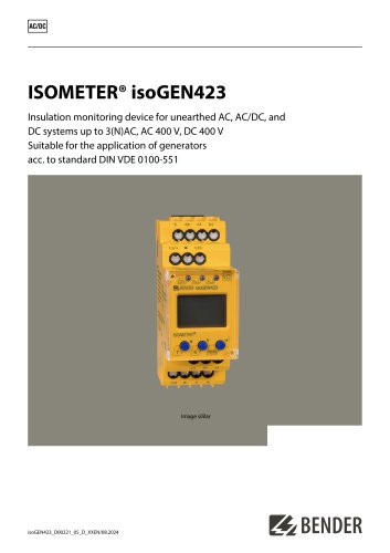 ISOMETER® isoGEN423
6 Pages
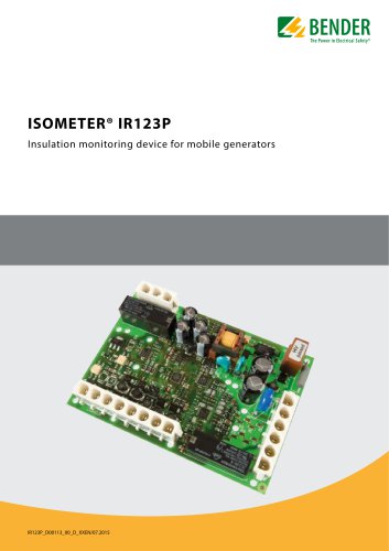 ISOMETER® IR123P
4 Pages
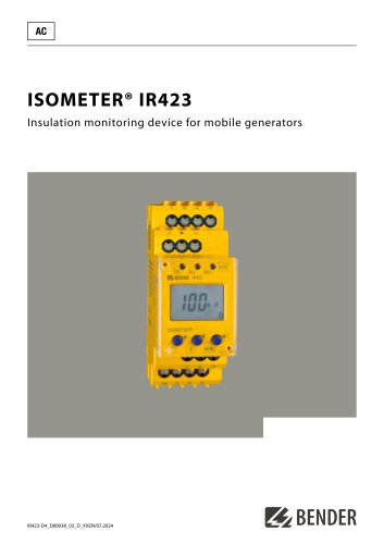 ISOMETER® IR423
6 Pages
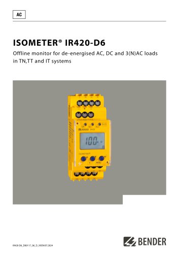 ISOMETER® IR420-D6
6 Pages
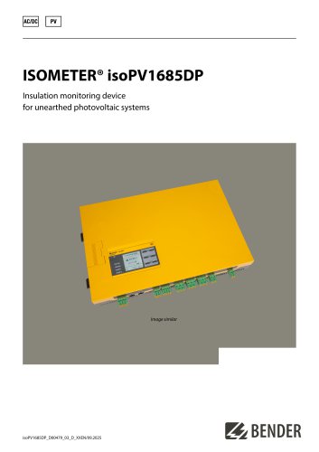 ISOMETER® isoPV1685DP
10 Pages
 ISOMETER® isoPV1685RTU
8 Pages
 ISOMETER® isoPV
8 Pages
 ISOMETER® isoLR275
6 Pages
 ISOMETER® isoMED427x-(PT)
6 Pages
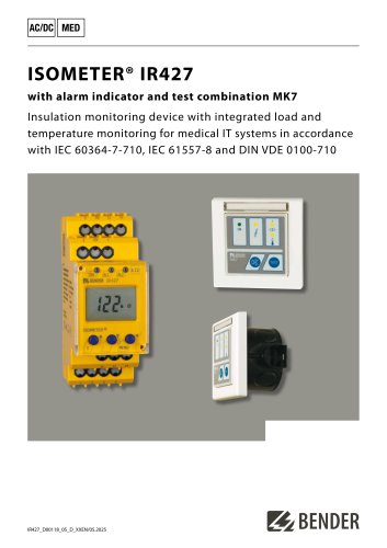 ISOMETER® IR427
8 Pages
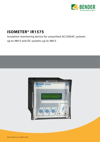 ISOMETER® IR1575
6 Pages
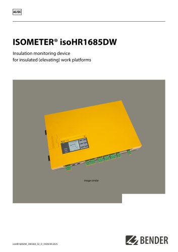 ISOMETER® isoHR1685DW
10 Pages
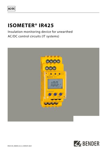 ISOMETER® IR425-D4
6 Pages
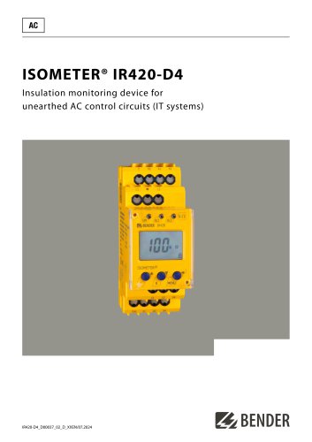 ISOMETER® IR420-D4
6 Pages
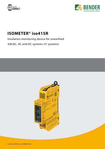
 ISOMETER® iso415R
2 Pages
 ISOMETER® IRDH275BM-7
6 Pages
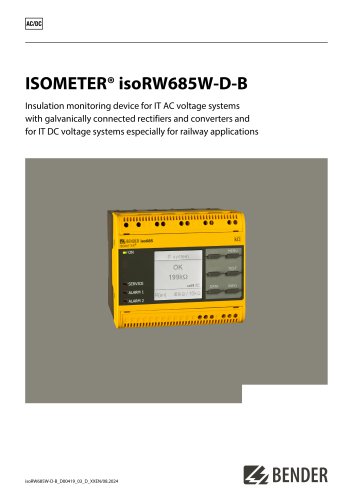 ISOMETER® isoRW685W-D-B
10 Pages
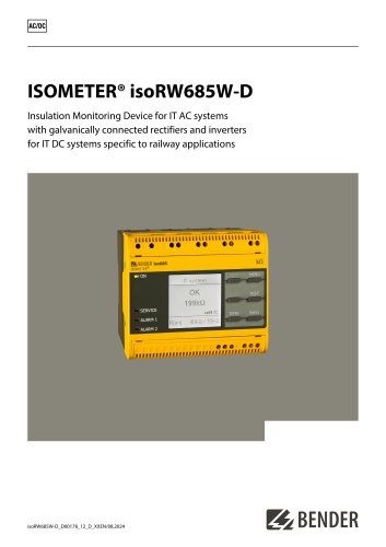 ISOMETER® isoRW685W-D
10 Pages
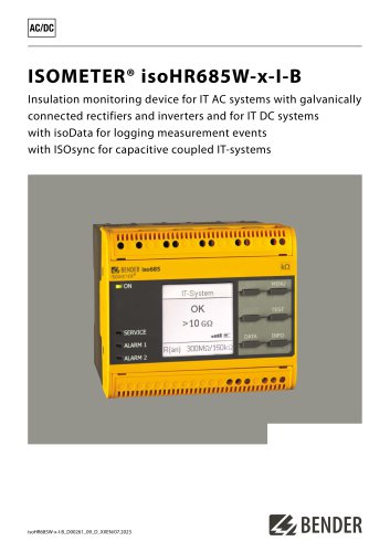 ISOMETER® isoHR685W-x-I-B
10 Pages
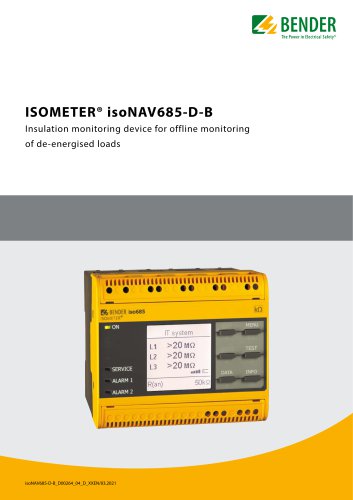 ISOMETER® isoNAV685-D-B
8 Pages
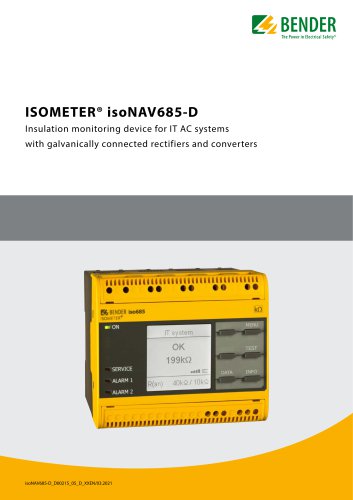 ISOMETER® isoNAV685-D
8 Pages
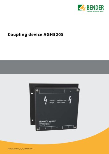 AGH520S
4 Pages
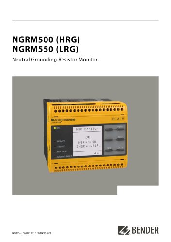 NGRM500 et NGRM550
12 Pages
 RCMS410
10 Pages
 RCMS425-D
10 Pages
 EDGE500
12 Pages
 Iso415R
4 Pages
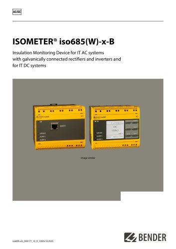 Iso685-x-B
12 Pages
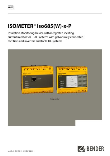 Iso685-x-P
14 Pages
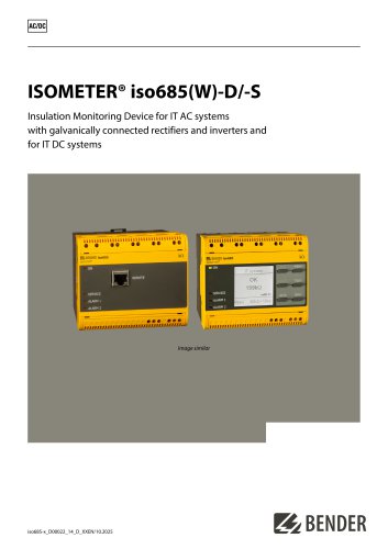 Iso685-x
12 Pages
 Data Centers
16 Pages
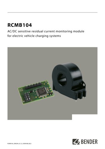 RCMB104
6 Pages
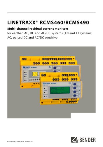 LINETRAXX® RCMS460 / RCMS490
14 Pages
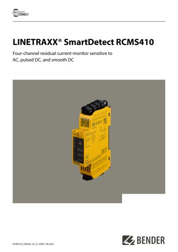
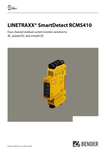 LINETRAXX® SmartDetect RCMS410
10 Pages
 Main Catalogue
486 Pages
- Power supply unit
- DC power supply
- AC/DC power supply
- Measuring device
- BENDER dry transformer
- Junction block
- CE power supply
- Cloud-based software
- Single-output power supply
- Portable tester
- Power supply for industrial applications
- Monitoring software solution
- Communication gateway
- LED display panel
- BENDER IEC transformer
- Compact power supply
- Automatic tester