- Catalogs
- BENDER GmbH & Co KG
- NGRM700 (HRG)/NGRM750 (LRG)
- Company
- Products
- Catalogs
- News & Trends
- Exhibitions
NGRM700 (HRG)/NGRM750 (LRG)
1 /12Pages
NGRM700 (HRG)/NGRM750 (LRG)
1 /12Pages
Catalog excerpts
Neutral Grounding Resistor Monitor
Open the catalog to page 1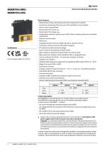
_Efc BENDER Neutral Grounding Resistor Monitor Device features • Determination of Rngr with passive and active measurement methods • Continuous monitoring of the Rngr even if the installation is de-energized; • Alarm or trip on ground fault • Monitoring of the voltage UNGR • Faulted phase indication (optional; up to 690 V direct coupling, otherwise via potential transformers) • Ethernet communication • Language selection (German, English GB and US, Spanish, French) • Test button (internal, external) with/without tripping • FFT analysis of neutral current and voltage • Pulser control for manual...
Open the catalog to page 2
Function The NGRM7… monitors NGR resistance RNGR, neutral voltage UNGR and current INGR. NGR resistance is monitored using an active and a passive procedure: active The device generates an active test pulse and measures RNGR even if the installation is de-energised. passive Only effective when installation is energized: The resistance RNGR is determined when INGR or UNGR exceeds an internal threshold. The device measures the existing current and voltage and calculates RNGR. In the case of the “auto” method, monitoring switches automatically between “active” and “passive” when the measured current...
Open the catalog to page 3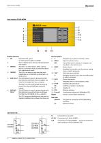
NGR monitor NGRM Kr BENDER Display elements 4 - TRIPPED The LED is on when the trip relay has been tripped due to an NGR fault, ground fault or a device error. 5 - NGR FAULT The LED flashes in case of a prewarning: NGR fault detected, NGR-fault relay has tripped, trip relay has not tripped yet (fNGR trip elapses). The LED is on when an NGR fault has been detected. Trip relay and NGR-fault relay have tripped. 6 - GROUND The LED flashes in case of a prewarning: ground FAULT fault detected, ground-fault relay has tripped, trip relay has not tripped yet ((gf trip elapses). on when power supply is...
Open the catalog to page 4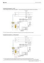
Connection star connection: Usys ≤ 690 V For these voltages, the phase monitor of the NGRM7… can be connected directly to the phase conductors to be monitored. Circuit breaker L1 Ground fault The “N” connection of the CD-series coupling device should be as close to the transformer star point as possible. Connection Star connection: Usys ≤ 690 V with pulser Circuit breaker L1 Ground fault X1 X1 Ethernet Pulser OUT RP = RPulser The “N” connection of the CD-series coupling device should be as close to the transformer star point as possible. An intermediate relay may be required between the power...
Open the catalog to page 5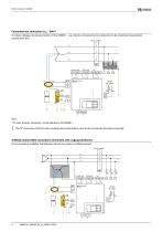
Connection star connection: Usys > 690 V For these voltages, the phase monitor of the NGRM7… can only be connected to the conductors to be monitored via potential transformers (PT). Circuit breaker Ground fault Note: * PT ratio "primary: secondary" can be adjusted in the NGRM7…. The “N” connection of the CD-series coupling device should be as close to the transformer star point as possible Artificial neutral (delta connection): Connection with a zigzag transformer If no star point is available, the following circuit can create an artificial neutral. Circuit breaker L1 L2 L3 Ground fault
Open the catalog to page 6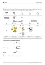
Measuring current transformer connection Depending on the system to be monitored, a suitable measuring current transformer has to be chosen. All common measuring current transformers (50 mA or 5 A on the secondary side) can be used. The following table helps you with the choice: System type Transformation ratio Bender measuring current transformer Measuring range (see CTUB103 manual) 5 A 100:1 10 A 200:1 25 A 500:1 Connecting cable CTAC… / CTAS… Any standard current transformer can be used. Connection of relays (ground-fault, NGR and trip relay) Ground-fault relay NGR-fault relay Trip relay The...
Open the catalog to page 7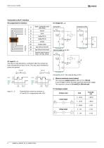
NGR monitor NGRM Kr BENDER Switch open closed Digital 1, active Reset, passive Test _n_r Switch open closed Digita| 1,active Reset, passive Test Connection to Q1, Q2: external relay or PLC. £ Observe maximum current values! The maximum output current on X1(+24 V) is 100 mA. In case of higher currents, the relays require an external 24 V supply. The maximum current on Q1 and Q2 is 300 mA each. Input I1...3: Potential-free contact to common or Analogue output
Open the catalog to page 8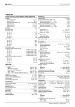
Technical Data Insulation coordination according to IEC 60664-1/IEC 60664-3/DIN EN 50178 Monitoring RNGR Measuring input RS < 33 V RMS Measuring range NGR (with RS = 20 kΩ) active 0…10 kΩ Measurement uncertainty for T = 0…+40 °C ±20 Ω Measurement uncertainty for T = –40…+70 °C ±40 Ω Measuring range NGR (with RS = 100 kΩ) active 0…10 kΩ Measurement uncertainty for T = 0…+40 °C ±30 Ω Measurement uncertainty for T = –40…+70 °C ±80 Ω HRG Setting range RNGR nom15 Ω…5 kΩ Response value RNGR nom 110…200 % RNGR nom LRG Setting range RNGR nom0.1…200 Ω Response value >RNGR nom200…500 Ω Response delay,...
Open the catalog to page 9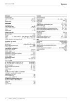
Digital inputs Galvanic separation Length connecting cables Uin Overload capacity Digital outputs Galvanic separation Length connecting cables Currents (sink) for each output Voltage Overload capacity Analogue output (M+) Operating principle linear Functions INGR, RNGR Current 0…20 mA (≤ 600 Ω), 4…20 mA (≤ 600 Ω), 0…400 μA (≤ 4 kΩ) Voltage 0…10 V (≥ 1 kΩ), 2…10 V (≥ 1 kΩ) Tolerance related to the current/voltage end value ±20 % Ground-fault, NGR, trip relay Switching elements Operating mode Electrical endurance, number of cycles Switching capacity Contact data acc. to IEC 60947-5-1 Rated operational...
Open the catalog to page 10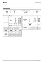
RBENDER Ordering information 11 All types and ordering informations of this series are available on our website
Open the catalog to page 11
RBENDER Bender GmbH & Co. KG • Germany Londorfer StraRe 65 • 35305 Grunberg Tel.: +49 6401 807-0 • [email protected] www.bender.de USA, Mexico, Central America • Exton PA, USA 800.356.4266 / 610.383.9200 • [email protected] www.bender.org Canada • Missisauga ON, Canada 800.243.2438 / 905.602.9990 [email protected] • www.bender-ca.com South America • Santiago de Chile © Bender GmbH & Co. KG, Germany Subject to change! The specified standards take into account the edition valid until 07.2023 unless otherwise indicated.
Open the catalog to page 12All BENDER GmbH & Co KG catalogs and technical brochures
 CD25000
4 Pages
 CD14400
4 Pages
 CD1000
4 Pages
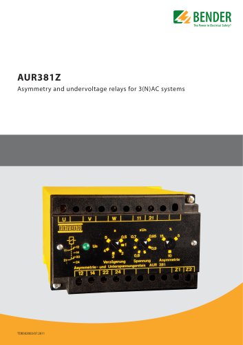 AUR381Z
4 Pages
 AN110
AN1104 Pages
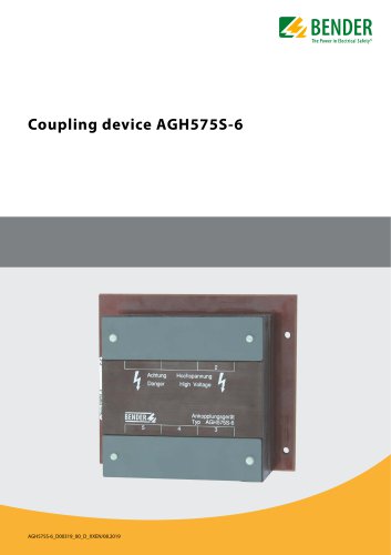 AGH575S-6
4 Pages
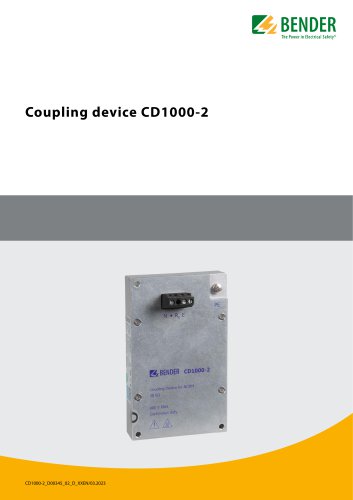 CD1000-2
4 Pages
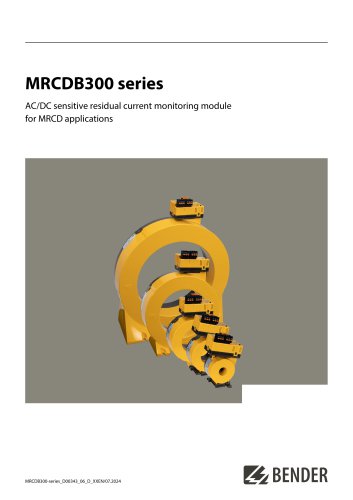 MRCDB300 series
12 Pages
 COMTRAXX® COM465IP/COM465DP
10 Pages
 ISOMETER® iso1685DP
10 Pages
 LINETRAXX® VMD420
6 Pages
 LINETRAXX® VMD423/VMD423H
6 Pages
 ISOMETER® iso685(W)-x-B
12 Pages
 ISOMETER® iso685
12 Pages
 UNIMET® 810ST
4 Pages
 UNIMET® 610ST
4 Pages
 UNIMET® 400ST
4 Pages
 UNIMET® 300ST
4 Pages
 AN111
AN1114 Pages
 AN450
AN4504 Pages
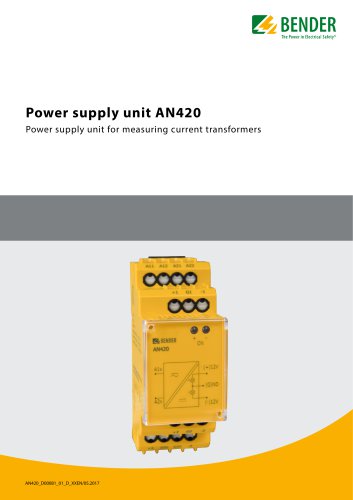 AN420
AN4204 Pages
 AN410
AN4104 Pages
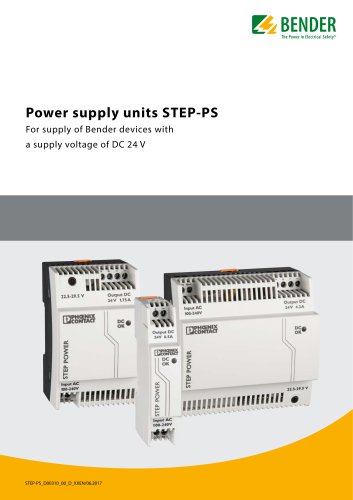 STEP-PS
8 Pages
 CTBC17 series
8 Pages
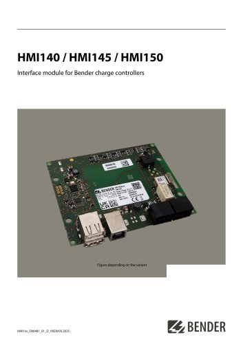 HMI140 / HMI145 / HMI150
6 Pages
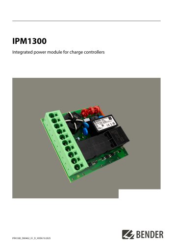 IPM1300
8 Pages
 CC613
CC6136 Pages
 ICC1324
8 Pages
 ICC1314
8 Pages
 AGH676S-4
4 Pages
 AGH520S
4 Pages
 AGH204S-4
4 Pages
 AGH150xx
4 Pages
 LINETRAXX® WF… series
4 Pages
 WS…, WS…-8000 series
4 Pages
 WR70x175S(P)…WR200x500S(P)
4 Pages
 WS50x80S…WS80x160S
4 Pages
 W0-S20…W5-S210 W10/600
4 Pages
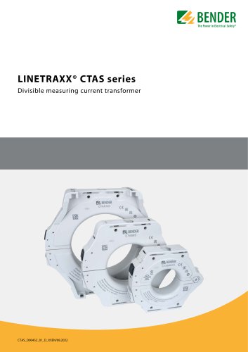 LINETRAXX® CTAS series
8 Pages
 LINETRAXX® CTBS25
4 Pages
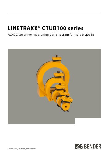 LINETRAXX® CTUB100 series
10 Pages
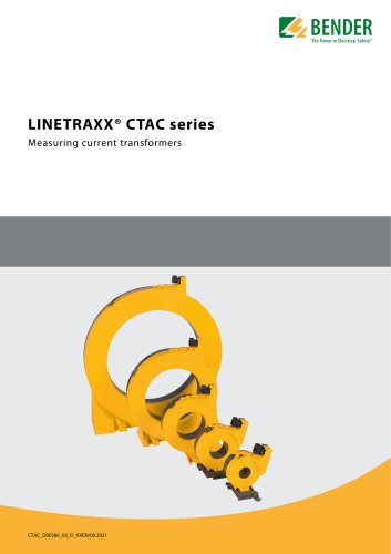 LINETRAXX® CTAC series
6 Pages
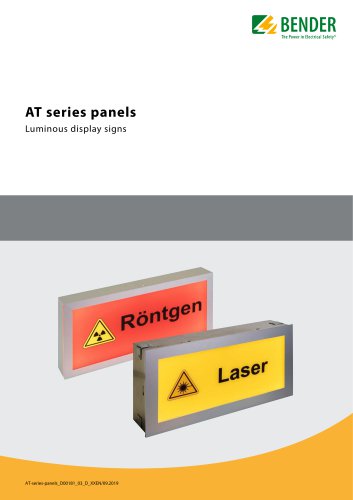 AT series
6 Pages
 COMTRAXX® MK2430
6 Pages
 COMTRAXX® CP305
12 Pages
 COMTRAXX® CP9xx
8 Pages
 DI-1DL
4 Pages
 SMO482P-12
4 Pages
 Signal converter SMI473
4 Pages
 DI-2USB
4 Pages
 COMTRAXX® COM463BC
7 Pages
 COMTRAXX® COM465ID
8 Pages
 COMTRAXX® EDGE500
12 Pages
 COMTRAXX® CP9…-I Series
10 Pages
 POWERSCOUT®
8 Pages
 LINETRAXX® GM420
6 Pages
 LINETRAXX® CMS460-D
10 Pages
 LINETRAXX® CMD420/CMD421
6 Pages
 LINETRAXX® CME420
6 Pages
 LINETRAXX® VMD258
6 Pages
 LINETRAXX® VMD461
10 Pages
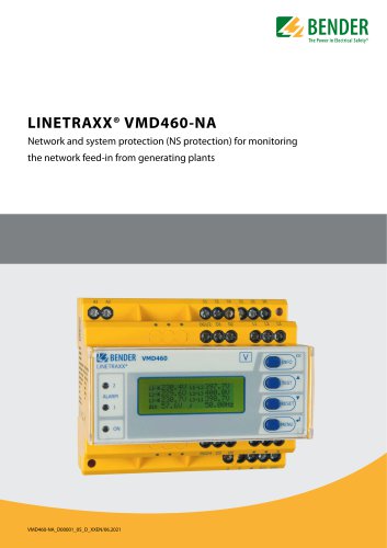 LINETRAXX® VMD460-NA
8 Pages
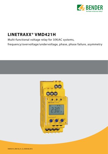 LINETRAXX® VMD421H
6 Pages
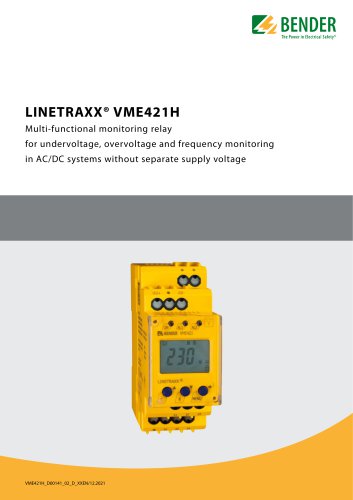 LINETRAXX® VME421H
6 Pages
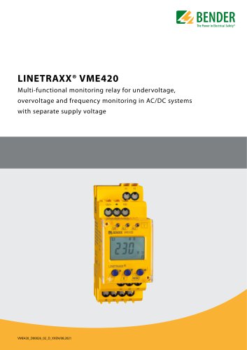 LINETRAXX® VME420
6 Pages
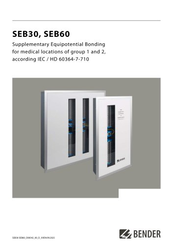 SEB30, SEB60
8 Pages
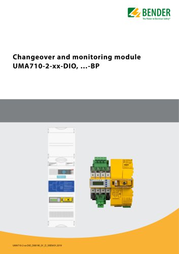 UMA710-2-xx-DIO, …-BP
6 Pages
 UMA710-2-…-ISO…
6 Pages
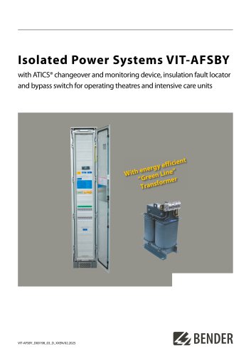 VIT-AFSBY
6 Pages
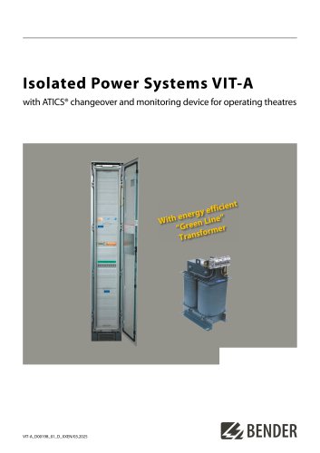 VIT-A
VIT-A6 Pages
 ATICS-2-…-DIO, ATICS-4-…-DIO
8 Pages
 LINETRAXX® CTUB103
6 Pages
 NGRM500 (HRG)/NGRM550 (LRG)
12 Pages
 RDC125-5S
12 Pages
 RCMB131-01
4 Pages
 RDC121
7 Pages
 RCMB123
7 Pages
 Residual current sensors
2 Pages
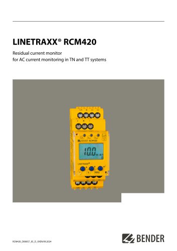 LINETRAXX® RCM420
6 Pages
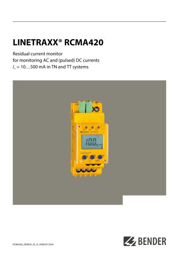 LINETRAXX® RCMA420
6 Pages
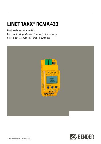 LINETRAXX® RCMA423
6 Pages
 LINETRAXX® MRCDB423
6 Pages
 RDC104-4
6 Pages
 RCMB104
6 Pages
 LINETRAXX® RCMB330
4 Pages
 LINETRAXX® RCMS150 series
8 Pages
 RCMB300-series
12 Pages
 LINETRAXX® RCMS460/RCMS490
14 Pages
 LINETRAXX® SmartDetect RCMS410
10 Pages
 IOM441-S / IOM441W-S
4 Pages
 EDS3090/-91/-92/-96
14 Pages
 ISOSCAN® EDS150/151
6 Pages
 ISOSCAN® EDS440/EDS441
16 Pages
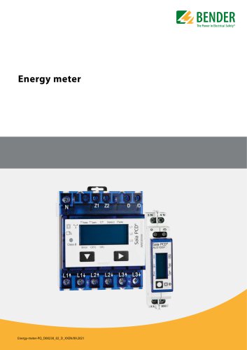 Energy meter
6 Pages
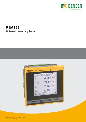 PEM353
8 Pages
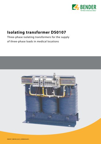 DS0107
6 Pages
 ESL0107
4 Pages
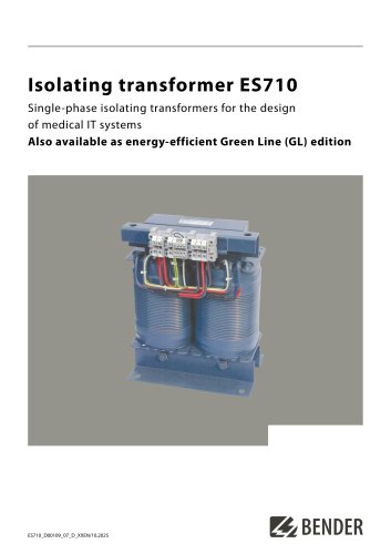 ES710
ES7108 Pages
 7204/7220/9604/9620
4 Pages
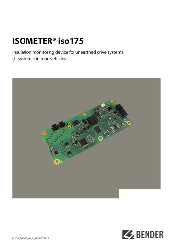 ISOMETER® iso175
8 Pages
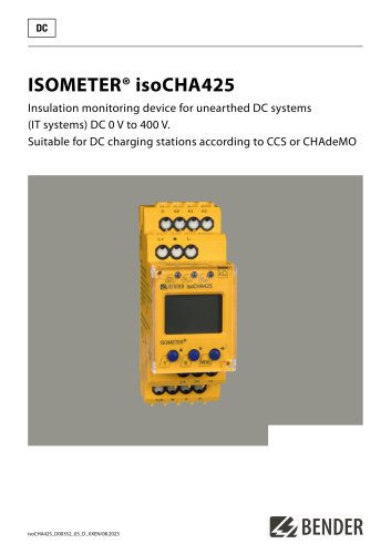 ISOMETER® isoCHA425
8 Pages
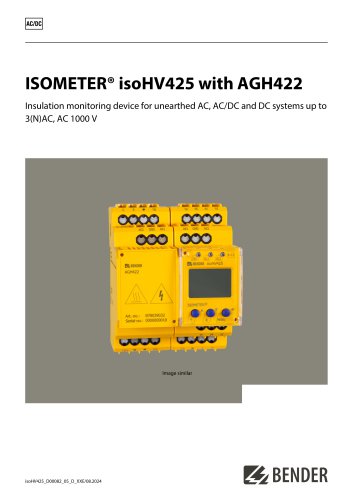 ISOMETER® isoHV425 with AGH422
10 Pages
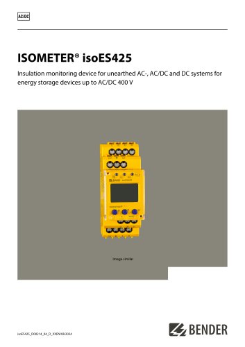 ISOMETER® isoES425
8 Pages
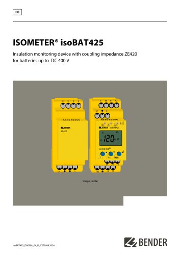 ISOMETER® isoBAT425
8 Pages
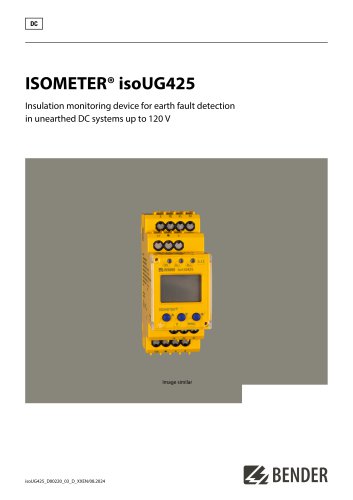 ISOMETER® isoUG425
6 Pages
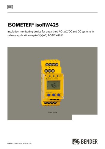 ISOMETER® isoRW425
8 Pages
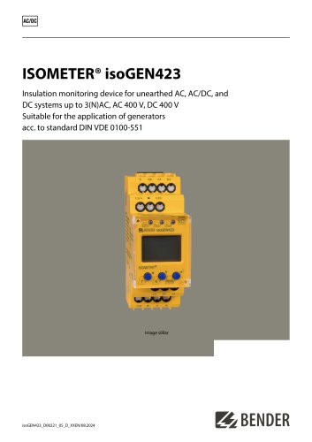 ISOMETER® isoGEN423
6 Pages
 ISOMETER® IR123P
4 Pages
 ISOMETER® IR423
6 Pages
 ISOMETER® IR420-D6
6 Pages
 ISOMETER® isoPV1685DP
10 Pages
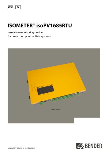 ISOMETER® isoPV1685RTU
8 Pages
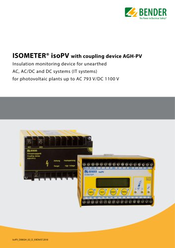 ISOMETER® isoPV
8 Pages
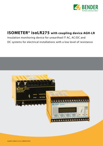 ISOMETER® isoLR275
6 Pages
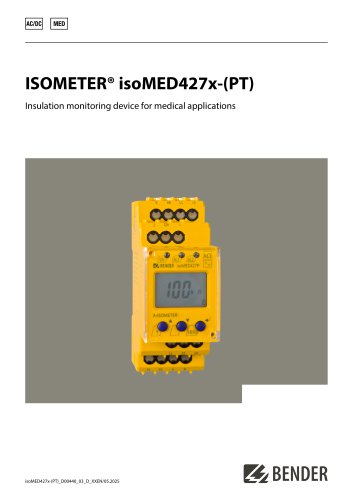 ISOMETER® isoMED427x-(PT)
6 Pages
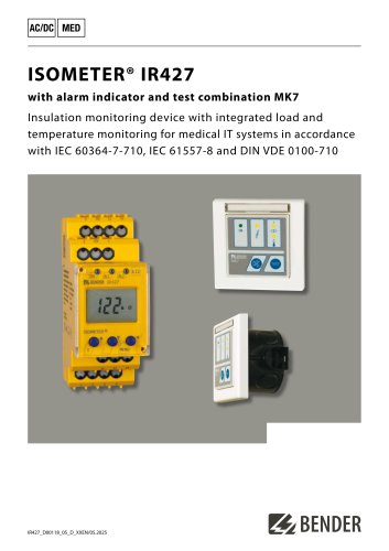 ISOMETER® IR427
8 Pages
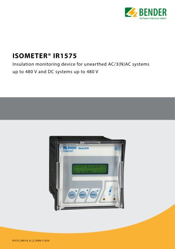 ISOMETER® IR1575
6 Pages
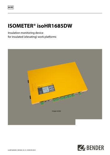 ISOMETER® isoHR1685DW
10 Pages
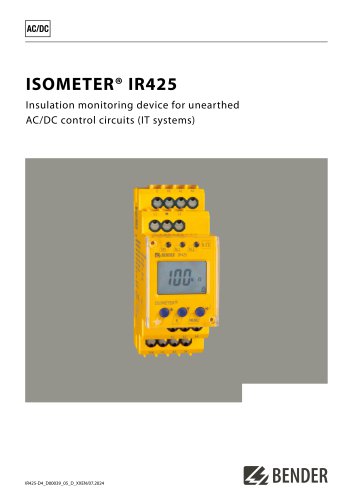 ISOMETER® IR425-D4
6 Pages
 ISOMETER® IR420-D4
6 Pages
 ISOMETER® iso415R
2 Pages
 ISOMETER® IRDH275BM-7
6 Pages
 ISOMETER® isoRW685W-D-B
10 Pages
 ISOMETER® isoRW685W-D
10 Pages
 ISOMETER® isoHR685W-x-I-B
10 Pages
 ISOMETER® isoNAV685-D-B
8 Pages
 ISOMETER® isoNAV685-D
8 Pages
 AGH520S
4 Pages
 NGRM500 et NGRM550
12 Pages
 RCM410R
8 Pages
 RCMS410
10 Pages
 RCMS425-D
10 Pages
 EDGE500
12 Pages
 Iso415R
4 Pages
 Iso685-x-B
12 Pages
 Iso685-x-P
14 Pages
 Iso685-x
12 Pages
 Data Centers
16 Pages
 RCMB104
6 Pages
 LINETRAXX® RCMS460 / RCMS490
14 Pages
 LINETRAXX® SmartDetect RCMS410
10 Pages
 Main Catalogue
486 Pages


- DC power supply
- AC/DC power supply
- Measuring device
- BENDER dry transformer
- CE power supply
- Cloud-based software
- Junction block
- Single-output power supply
- Power supply for industrial applications
- Portable tester
- Monitoring software solution
- Communication gateway
- LED display panel
- BENDER IEC transformer
- Power supply with overload protection
- Compact power supply