- Catalogs
- BENDER GmbH & Co KG
- LINETRAXX® VMD460-NA
- Company
- Products
- Catalogs
- News & Trends
- Exhibitions
LINETRAXX® VMD460-NA
1 /8Pages
LINETRAXX® VMD460-NA
1 /8Pages
Catalog excerpts

Network and system protection (NS protection) for monitoring the network feed-in from generating plants
Open the catalog to page 1
LINETRAXX® VMD460-NA Network and system protection (NS protection) for monitoring the network feed-in from generating plants Device features • Monitoring of different system types: 1AC, 3AC, 3NAC • Continuous monitoring of the phase voltage and line-to-line voltage • (Re)connection and monitoring of the conditions • Reconnection after - short interruptions - df/dt detection (ROCOF) - vector shift detection • Voltage protection functions U<, U<<, U>> and U> • Frequency protection functions f<, f<<, f>> and f> • Islanding detection df/dt (ROCOF), vector shift detection • Unbalance detection • Monitoring...
Open the catalog to page 2
Network and system protection (NS protection) LINETRAXX® VMD460 Standard/application guide • VDE-AR-N 4105:2018-09 • VDE-AR-N 4105:2011-08 • VDE-AR-N 4110:2018-11 • BDEW-Richtlinie 2008 einschl. Ergänzungen bis 01.2013 • DIN V VDE V 0126-1-1(:2016-06, /A1:2012-02) • CEI 0-21 (:2012-06, :V1:2012-12, :V2:2013-12, :2014-09, :V1:2014-12, :2016-07, V1:2017-07) • C10/11:2012-06 • G98/1-4:2019 • G83/2:2012 • G99/1-4:2019 • G59/3:2013 • G59/2(:2010, -1:2011 • UL File No. E173157 Schematic diagram Generating unit 1 interface switch with integrated Central interface switch Generating unit 2 interface switch...
Open the catalog to page 3
Network and system protection (NS protection) LINETRAXX® VMD460 Operating elements 2 - “ ON” LED (green): lights when the voltage supply is available and the device is in operation or flashes in case of a system error message (external watchdog). 1- B oth alarm LEDs “AL1” and “AL2”: light up in case of a limit value violation of voltage and frequency. 3 - Backlit LC display 4 - “INFO” button 5- U se the “TEST” button to run a manual self test which triggers both alarm relays (trigger test to check the coupling switches). In addition, fault simulation will be carried out with documentation of...
Open the catalog to page 4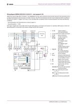
Network and system protection (NS protection) LINETRAXX® VMD460 Wiring diagram VMD460 (VDE-AR-N 4110:2018-11 – basic program 4110) Within the scope of VDE-AR-N 4110:2018-11, the VMD460-NA can be used as protective disconnection device for the generating unit or as higher-level protective disconnection, the latter, however, only if the Q-U protection function may be dispensed with. According to VDE-AR-N 4110:2018-11 chapter 10.3.3.4 par. 5, this is possible after consultation with the network operator and under the following conditions: • Generating plants with limited dynamic network support...
Open the catalog to page 5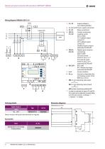
Network and system protection (NS protection) LINETRAXX® VMD460 Z BENDER 2 - L1, L2, L3, N Power supply connection D1: Feedback signal contact K1 D2: Feedback signal contact K2 (feedback signal contacts optionally NC/NO/off)* Digital inputs (external monitoring) D4: external signal (CEI 0-21 8.6.2.1.2)** (optionally NC/NO/off)* RTG: GND RT1: Remote trip input (optionally NC/NO/off)* Service interface Activate or deactivate the terminating resistor of the BMS bus (120 Q ) NO (in non-operating state open) NC (in non-operating state closed) off (contact monitoring switched off) In order to evaluate...
Open the catalog to page 6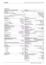
Network and system protection (NS protection) LINETRAXX® VMD460 Technical data Rated impulse voltage/ Overvoltage category 6 kV/III Protective separation (reinforced insulation) between Digital inputs Monitoring of potential-free contacts or voltage inputs: Supply voltage Nominal supply voltage US open = high; > 6.< 30 V feedback signal contact K1 feedback signal contact K2 local control (mode) external signal (mode) remote trip GND Power consumption at AC 230 V maximum Max. length of the connecting cables of digital inputs Measuring circuit Nominal system voltage Un (r.m.s. value) (L-N) Nominal...
Open the catalog to page 7
BENDER Group VMD460-NA_D00001_05_D_XXEN/06.2021 / © Bender GmbH & Co. KG, Germany – subject to change! The specified standards take into account the edition valid until 06.2021 unless otherwise indicated. Bender GmbH & Co. KG P.O. Box 1161 • 35301 Grünberg • Germany Londorfer Straße 65 • 35305 Grünberg • Germany Tel.: +49 6401 807-0 • Fax: +49 6401 807-259 E-mail: [email protected]
Open the catalog to page 8All BENDER GmbH & Co KG catalogs and technical brochures
 CD25000
4 Pages
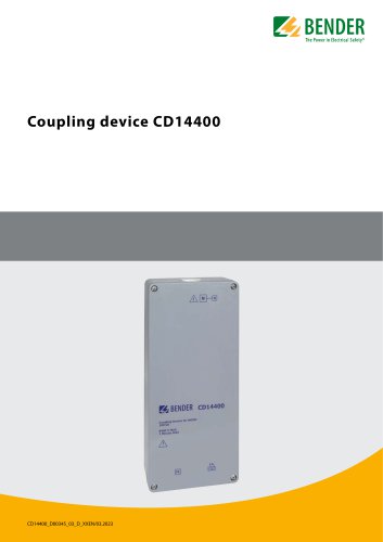 CD14400
4 Pages
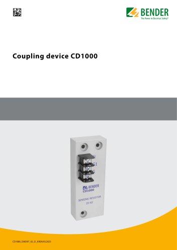 CD1000
4 Pages
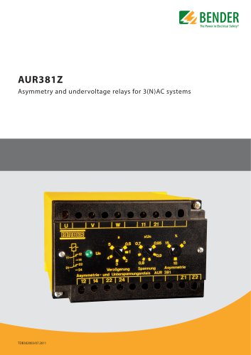 AUR381Z
4 Pages
 AN110
AN1104 Pages
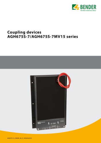
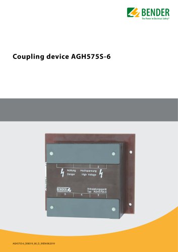 AGH575S-6
4 Pages
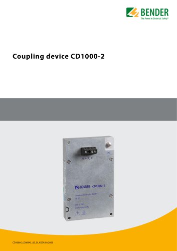 CD1000-2
4 Pages
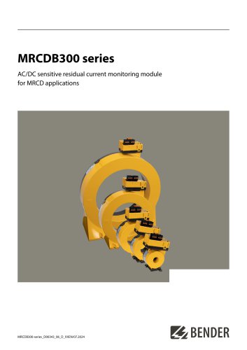 MRCDB300 series
12 Pages
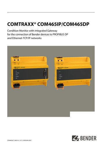 COMTRAXX® COM465IP/COM465DP
10 Pages
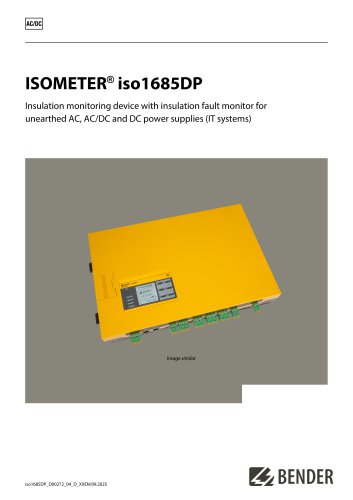 ISOMETER® iso1685DP
10 Pages
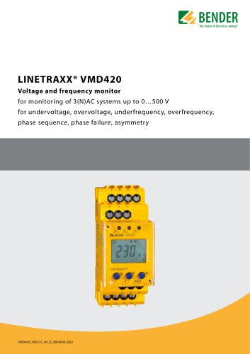 LINETRAXX® VMD420
6 Pages
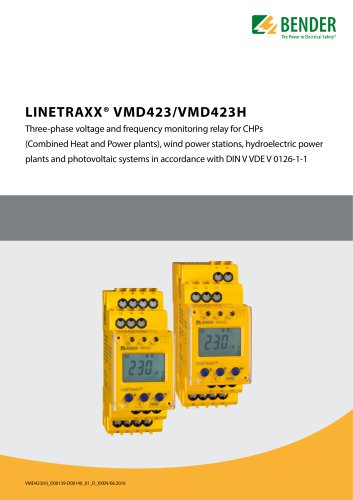 LINETRAXX® VMD423/VMD423H
6 Pages
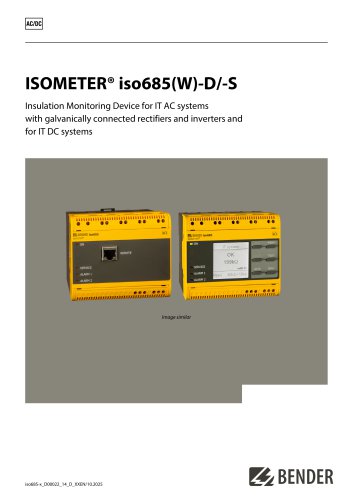
 ISOMETER® iso685(W)-x-B
12 Pages
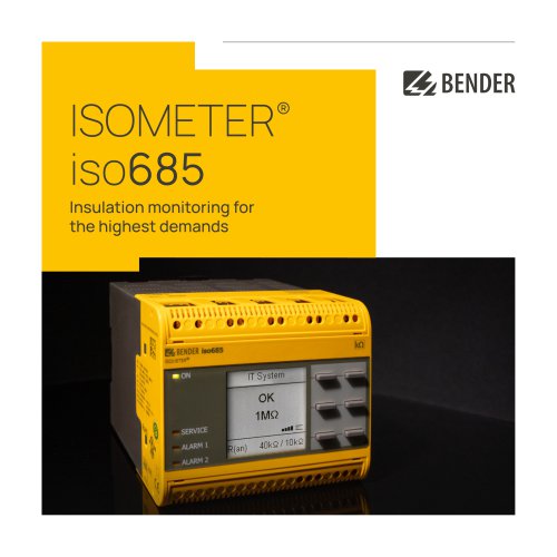 ISOMETER® iso685
12 Pages
 UNIMET® 810ST
4 Pages
 UNIMET® 610ST
4 Pages
 UNIMET® 400ST
4 Pages
 UNIMET® 300ST
4 Pages
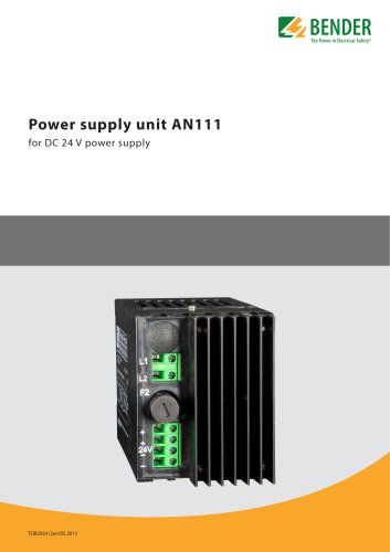 AN111
AN1114 Pages
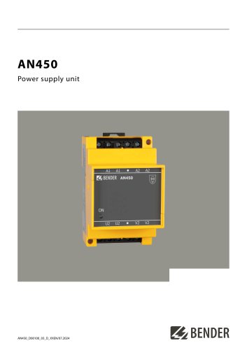 AN450
AN4504 Pages
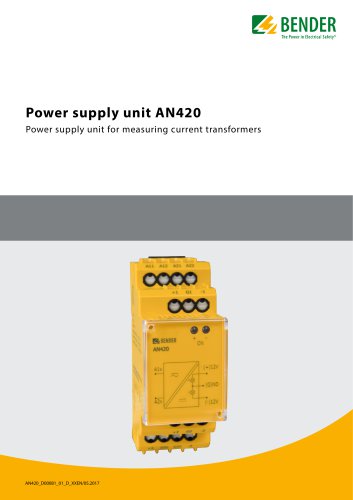 AN420
AN4204 Pages
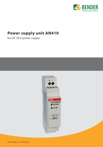 AN410
AN4104 Pages
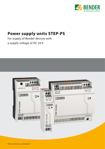 STEP-PS
8 Pages
 CTBC17 series
8 Pages
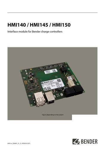 HMI140 / HMI145 / HMI150
6 Pages
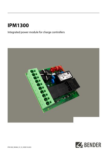 IPM1300
8 Pages
 CC613
CC6136 Pages
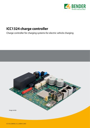 ICC1324
8 Pages
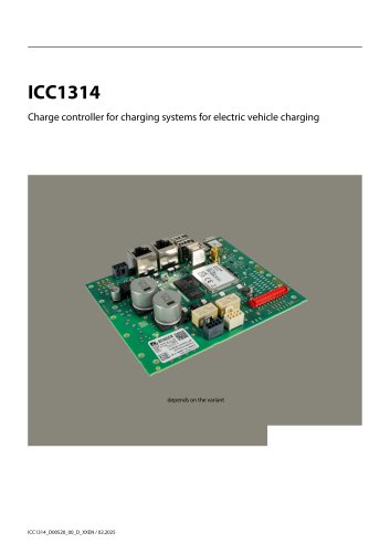 ICC1314
8 Pages
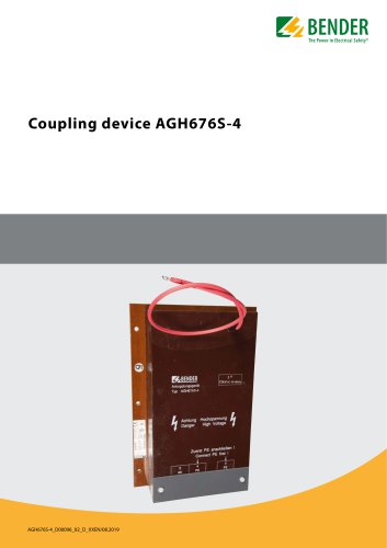 AGH676S-4
4 Pages
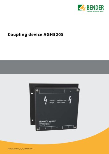
 AGH520S
4 Pages
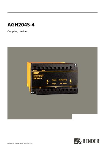 AGH204S-4
4 Pages
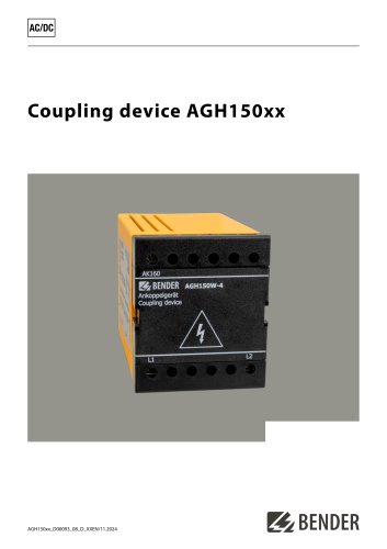 AGH150xx
4 Pages
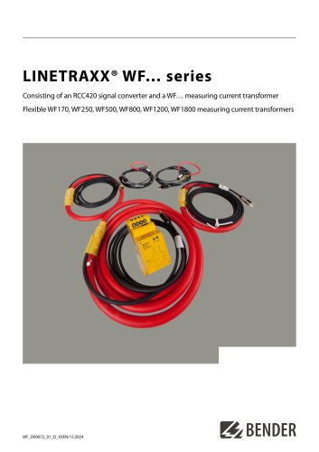 LINETRAXX® WF… series
4 Pages
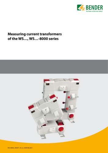 WS…, WS…-8000 series
4 Pages
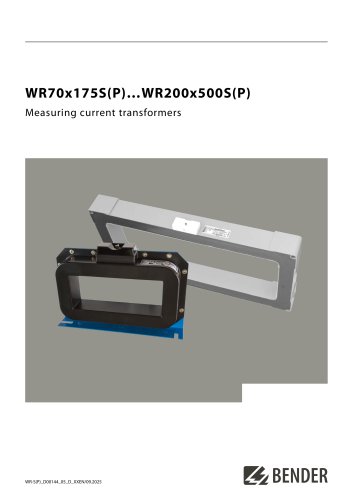 WR70x175S(P)…WR200x500S(P)
4 Pages
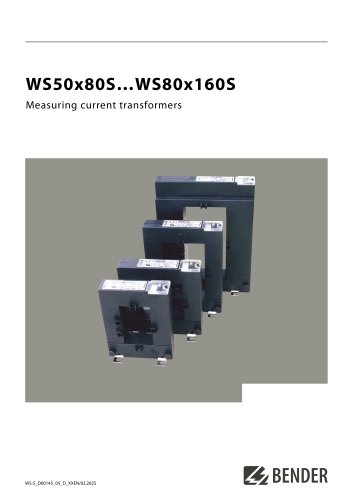 WS50x80S…WS80x160S
4 Pages
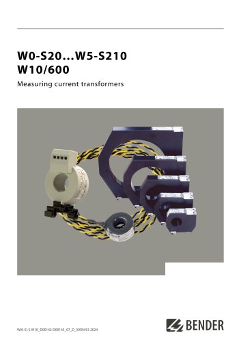 W0-S20…W5-S210 W10/600
4 Pages
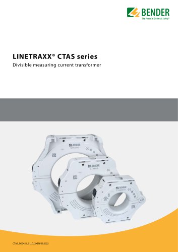 LINETRAXX® CTAS series
8 Pages
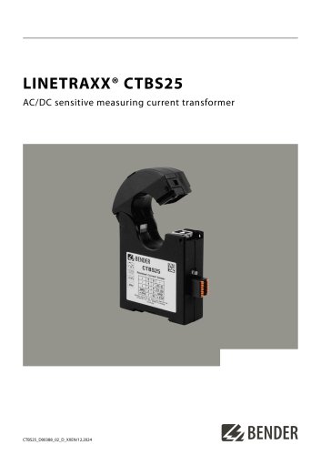 LINETRAXX® CTBS25
4 Pages
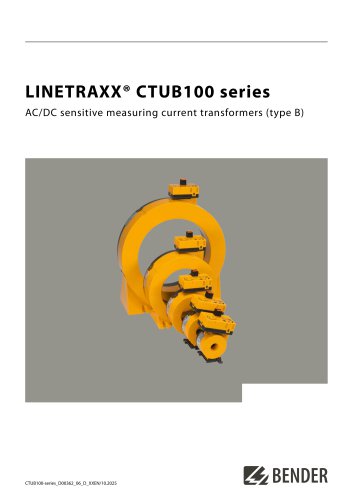 LINETRAXX® CTUB100 series
10 Pages
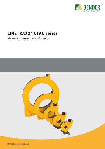 LINETRAXX® CTAC series
6 Pages
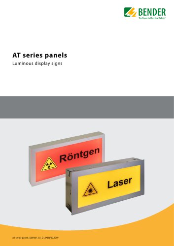 AT series
6 Pages
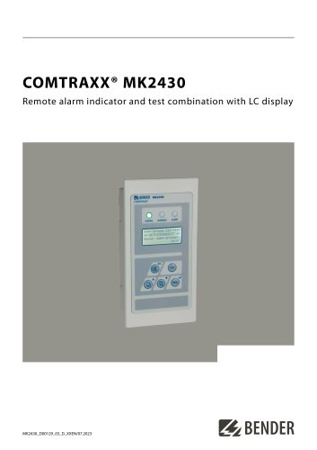 COMTRAXX® MK2430
6 Pages
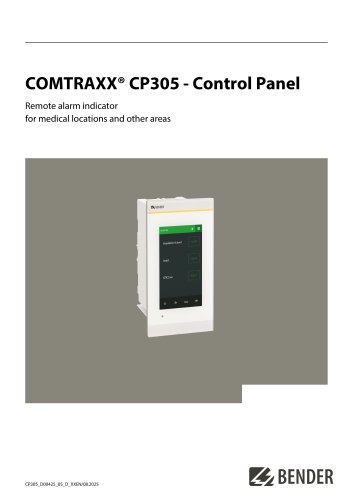 COMTRAXX® CP305
12 Pages
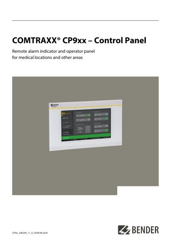 COMTRAXX® CP9xx
8 Pages
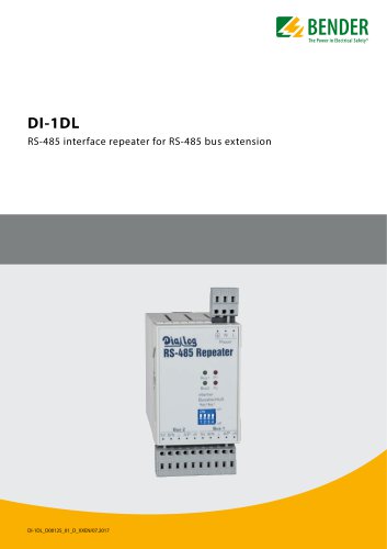 DI-1DL
4 Pages
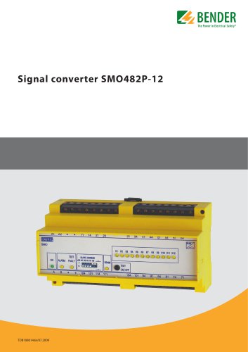 SMO482P-12
4 Pages
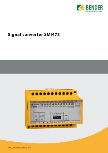 Signal converter SMI473
4 Pages
 DI-2USB
4 Pages
 COMTRAXX® COM463BC
7 Pages
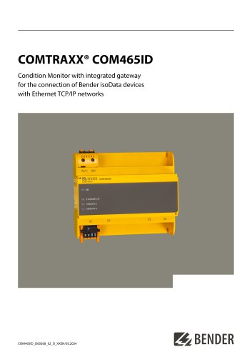 COMTRAXX® COM465ID
8 Pages
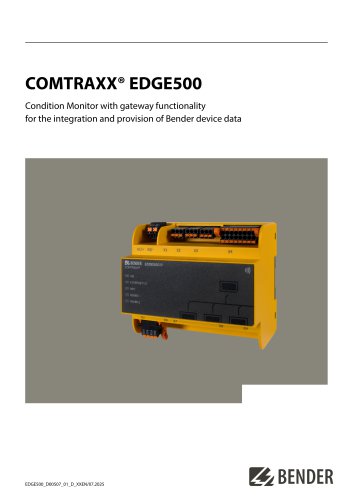 COMTRAXX® EDGE500
12 Pages
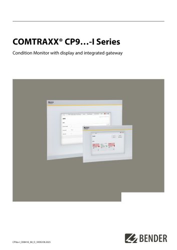 COMTRAXX® CP9…-I Series
10 Pages
 POWERSCOUT®
8 Pages
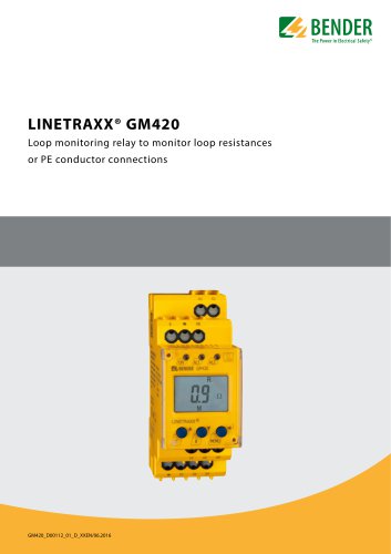 LINETRAXX® GM420
6 Pages
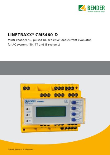 LINETRAXX® CMS460-D
10 Pages
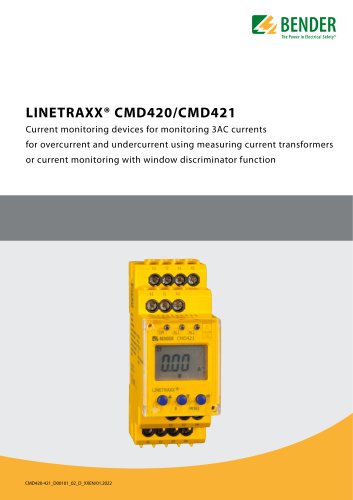 LINETRAXX® CMD420/CMD421
6 Pages
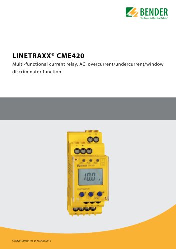 LINETRAXX® CME420
6 Pages
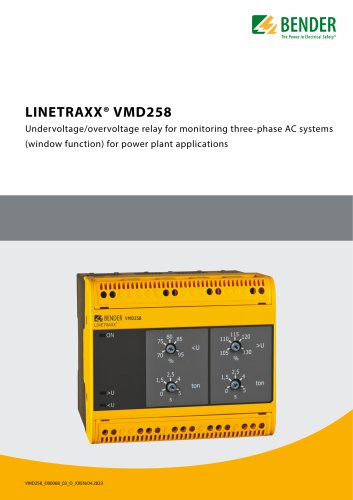 LINETRAXX® VMD258
6 Pages
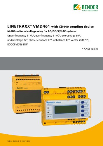 LINETRAXX® VMD461
10 Pages
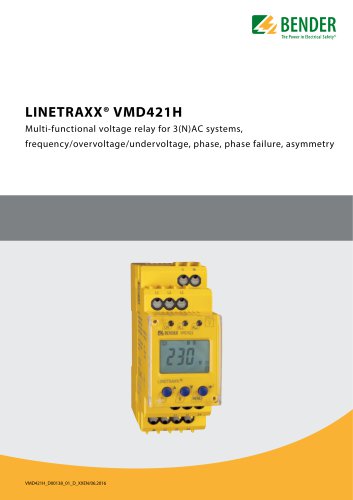 LINETRAXX® VMD421H
6 Pages
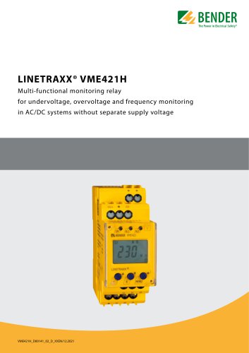 LINETRAXX® VME421H
6 Pages
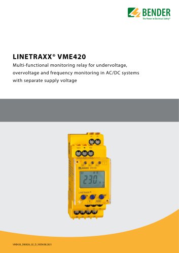 LINETRAXX® VME420
6 Pages
 SEB30, SEB60
8 Pages
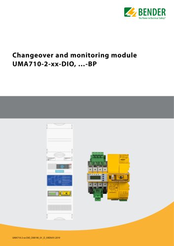 UMA710-2-xx-DIO, …-BP
6 Pages
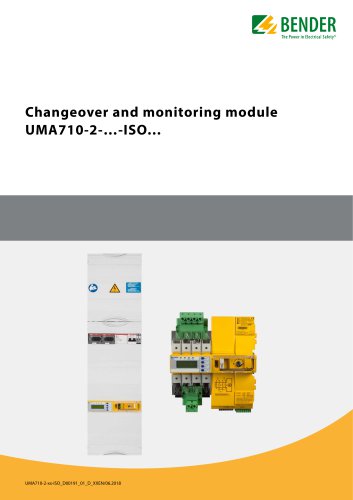 UMA710-2-…-ISO…
6 Pages
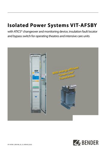 VIT-AFSBY
6 Pages
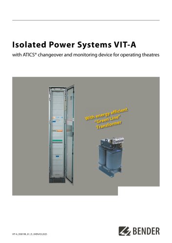 VIT-A
VIT-A6 Pages
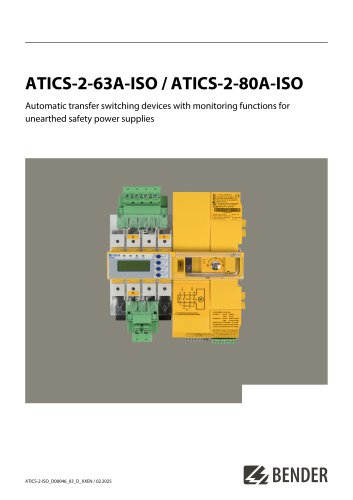
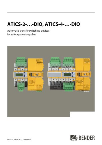 ATICS-2-…-DIO, ATICS-4-…-DIO
8 Pages
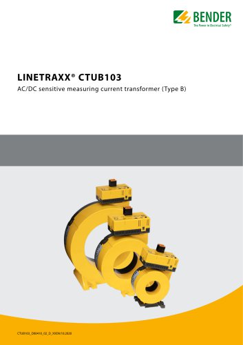 LINETRAXX® CTUB103
6 Pages
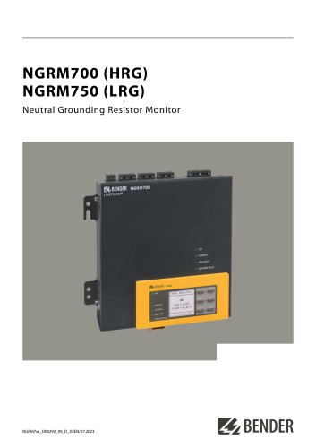 NGRM700 (HRG)/NGRM750 (LRG)
12 Pages
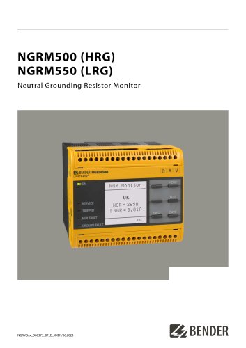
 NGRM500 (HRG)/NGRM550 (LRG)
12 Pages
 RDC125-5S
12 Pages
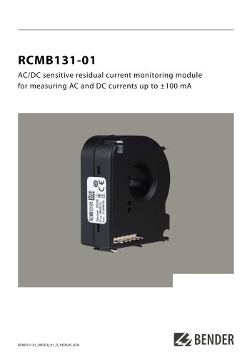 RCMB131-01
4 Pages
 RDC121
7 Pages
 RCMB123
7 Pages
 Residual current sensors
2 Pages
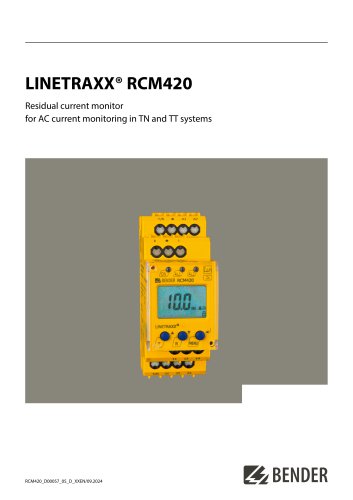 LINETRAXX® RCM420
6 Pages
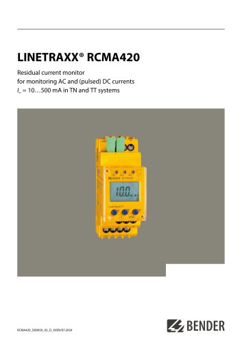 LINETRAXX® RCMA420
6 Pages
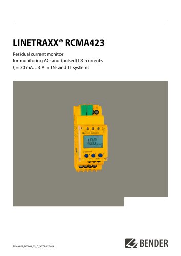 LINETRAXX® RCMA423
6 Pages
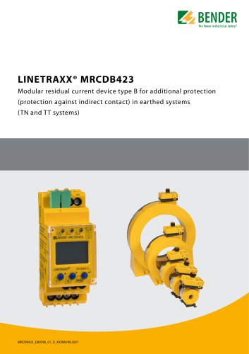 LINETRAXX® MRCDB423
6 Pages
 RDC104-4
6 Pages
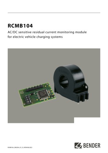
 RCMB104
6 Pages
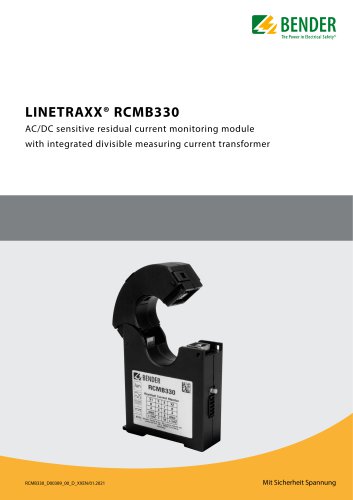 LINETRAXX® RCMB330
4 Pages
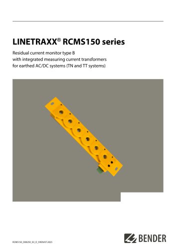 LINETRAXX® RCMS150 series
8 Pages
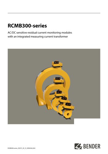 RCMB300-series
12 Pages
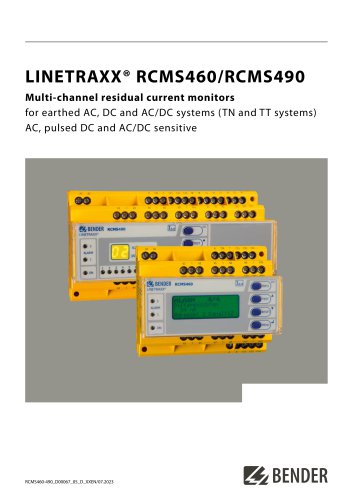 LINETRAXX® RCMS460/RCMS490
14 Pages
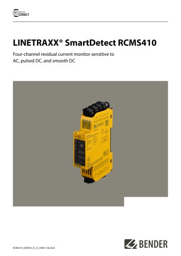
 LINETRAXX® SmartDetect RCMS410
10 Pages
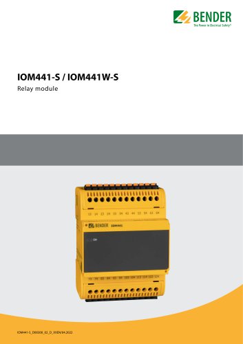 IOM441-S / IOM441W-S
4 Pages
 EDS3090/-91/-92/-96
14 Pages
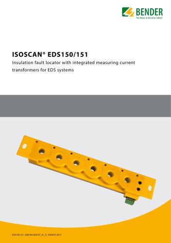 ISOSCAN® EDS150/151
6 Pages
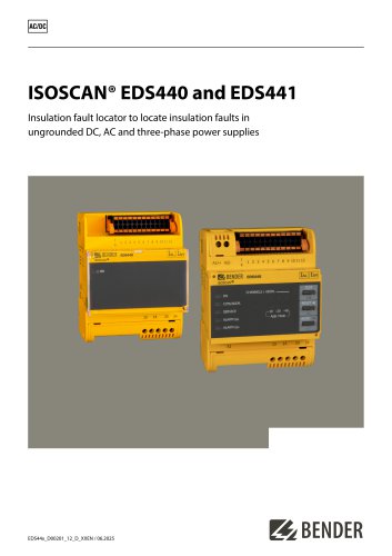 ISOSCAN® EDS440/EDS441
16 Pages
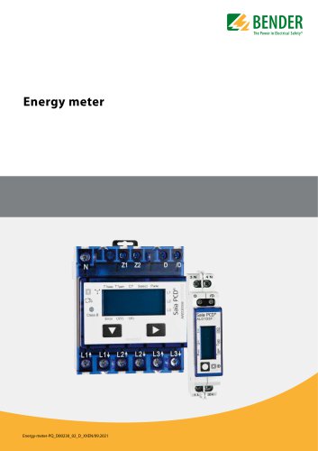 Energy meter
6 Pages
 PEM353
8 Pages
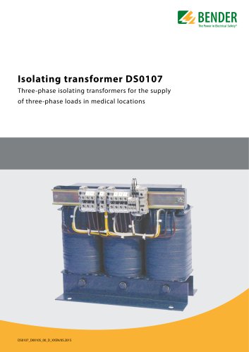 DS0107
6 Pages
 ESL0107
4 Pages
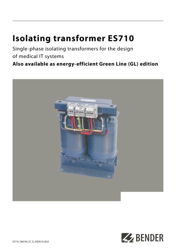 ES710
ES7108 Pages
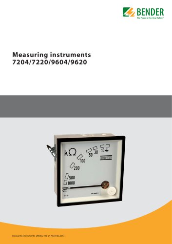 7204/7220/9604/9620
4 Pages
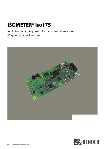 ISOMETER® iso175
8 Pages
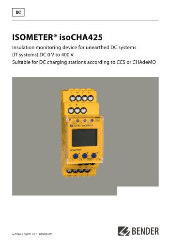 ISOMETER® isoCHA425
8 Pages
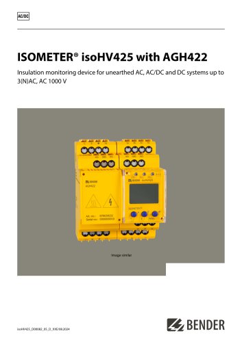 ISOMETER® isoHV425 with AGH422
10 Pages
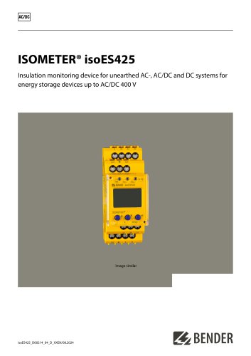 ISOMETER® isoES425
8 Pages
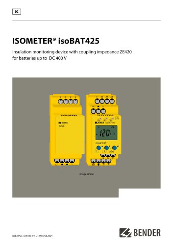 ISOMETER® isoBAT425
8 Pages
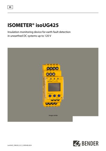 ISOMETER® isoUG425
6 Pages
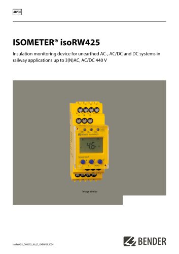 ISOMETER® isoRW425
8 Pages
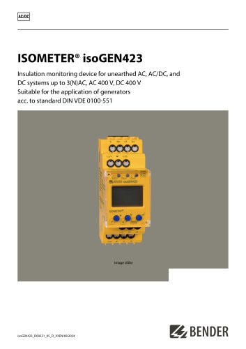 ISOMETER® isoGEN423
6 Pages
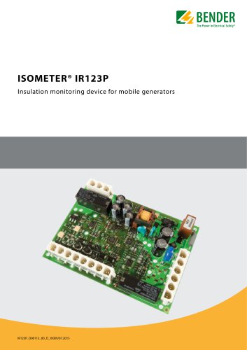 ISOMETER® IR123P
4 Pages
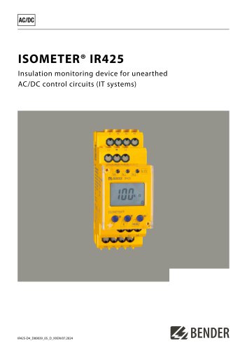
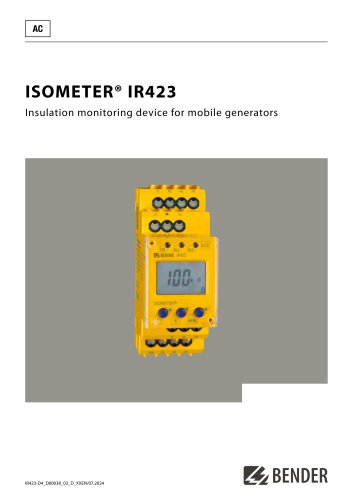 ISOMETER® IR423
6 Pages
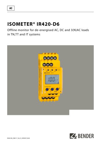 ISOMETER® IR420-D6
6 Pages
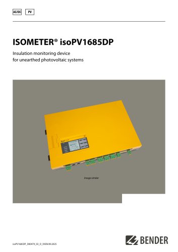 ISOMETER® isoPV1685DP
10 Pages
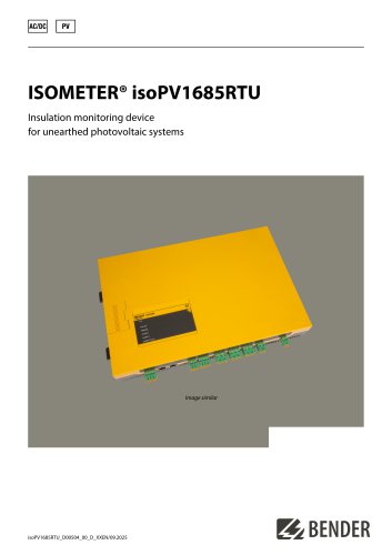 ISOMETER® isoPV1685RTU
8 Pages
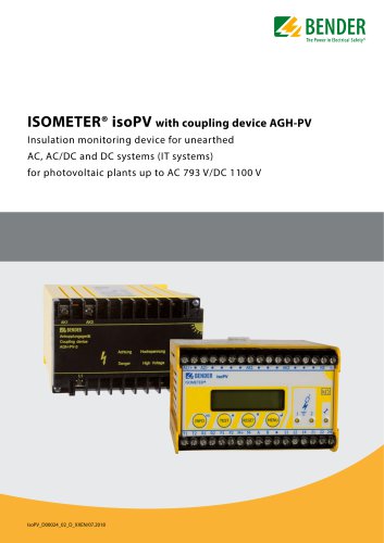 ISOMETER® isoPV
8 Pages
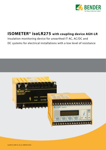 ISOMETER® isoLR275
6 Pages
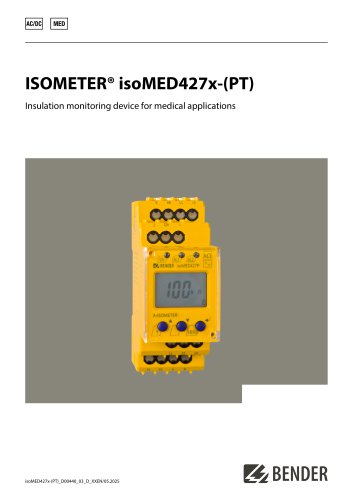 ISOMETER® isoMED427x-(PT)
6 Pages
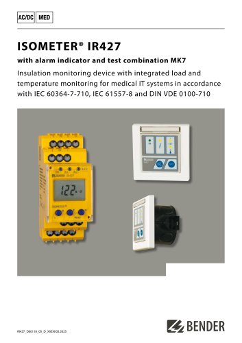 ISOMETER® IR427
8 Pages
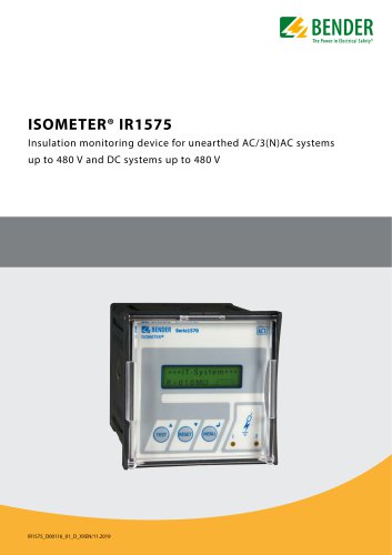 ISOMETER® IR1575
6 Pages
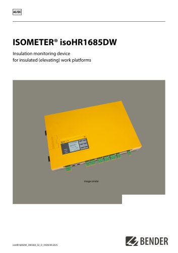 ISOMETER® isoHR1685DW
10 Pages
 ISOMETER® IR425-D4
6 Pages
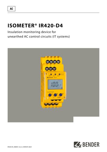 ISOMETER® IR420-D4
6 Pages
 ISOMETER® iso415R
2 Pages
 ISOMETER® IRDH275BM-7
6 Pages
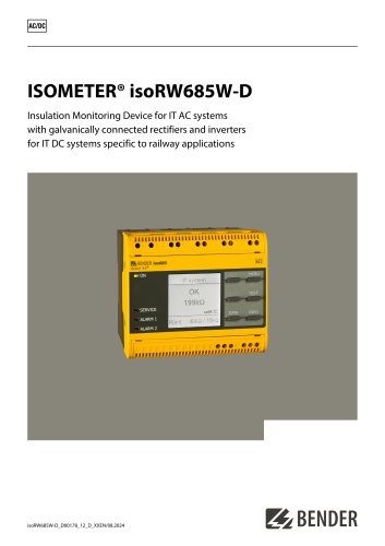
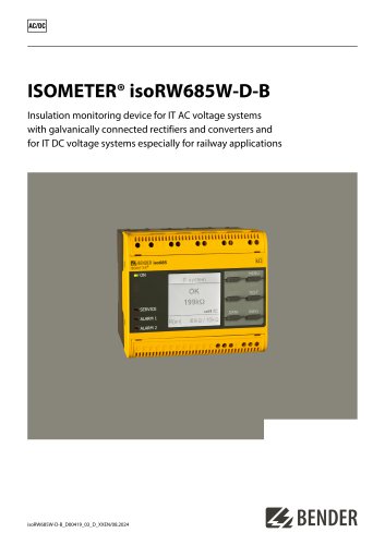 ISOMETER® isoRW685W-D-B
10 Pages
 ISOMETER® isoRW685W-D
10 Pages
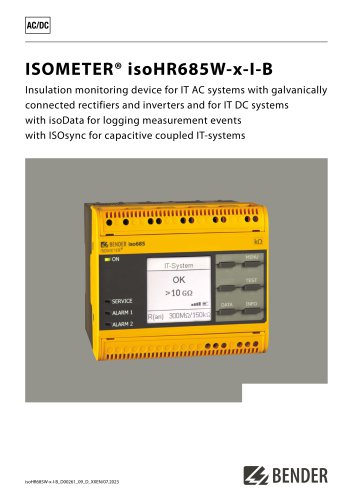 ISOMETER® isoHR685W-x-I-B
10 Pages
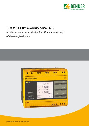 ISOMETER® isoNAV685-D-B
8 Pages
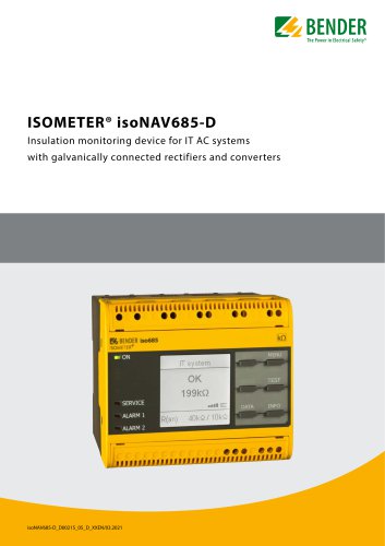 ISOMETER® isoNAV685-D
8 Pages
 AGH520S
4 Pages
 NGRM500 et NGRM550
12 Pages
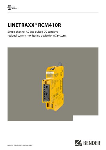 RCM410R
8 Pages
 RCMS410
10 Pages
 RCMS425-D
10 Pages
 EDGE500
12 Pages
 Iso415R
4 Pages
 Iso685-x-B
12 Pages
 Iso685-x-P
14 Pages
 Iso685-x
12 Pages
 Data Centers
16 Pages
 RCMB104
6 Pages
 LINETRAXX® RCMS460 / RCMS490
14 Pages
 LINETRAXX® SmartDetect RCMS410
10 Pages
 Main Catalogue
486 Pages

- DC power supply
- AC/DC power supply
- BENDER transformer
- Measuring device
- BENDER dry transformer
- CE power supply
- Cloud-based software
- Junction block
- Single-output power supply
- Power supply for industrial applications
- Portable tester
- Monitoring software solution
- Communication gateway
- LED display panel
- BENDER current transformer
- BENDER IEC transformer
- Power supply with overload protection
- Compact power supply