- Catalogs
- BENDER GmbH & Co KG
- ISOSCAN® EDS440/EDS441
- Company
- Products
- Catalogs
- News & Trends
- Exhibitions
ISOSCAN® EDS440/EDS441
1 /16Pages
ISOSCAN® EDS440/EDS441
1 /16Pages
Catalog excerpts

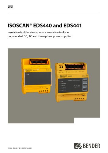
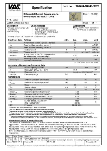
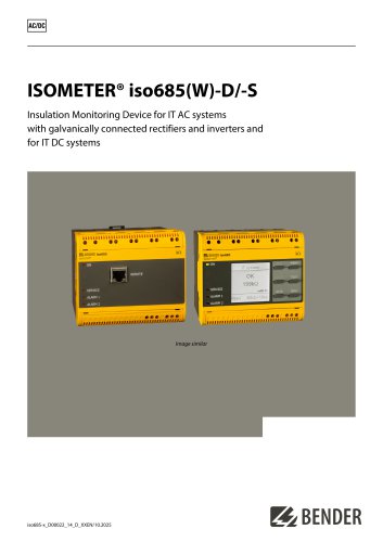
ISOSCAN® EDS440 and EDS441 Insulation fault locator to locate insulation faults in ungrounded DC, AC and three-phase power supplies
Open the catalog to page 1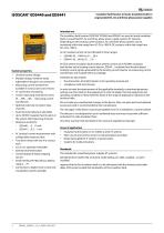
ISOSCAN® EDS440 and EDS441 Insulation fault locator to locate insulation faults in ungrounded DC, AC and three-phase power supplies System properties • Universal system design • Modular design, therefore easily adjustable to the given circumstances • Measuring current transformers available in various sizes and versions • Twelve measuring channels for series W..., WR..., WS... measuring current transformers • Optional extension by twelve relay channels • Fault memory behaviour selectable • Up to 50 EDS insulation fault locators in the system, 600 measuring channels • Response sensitivity: • AC...
Open the catalog to page 2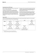
When an insulation monitoring device detects an insulation fault, it starts the insulation fault location. In the event of a first insulation fault, an undefined residual current flows in IT systems, which is primarily defined by the system leakage capacitances and the value of the insulation fault. The basic idea of insulation fault location is therefore to generate a defined locating current IL that flows through the insulation fault. The locating current is driven by the system voltage and can be located in the faulty outgoing circuit using the measuring current transformer. The locating current...
Open the catalog to page 3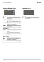
Status LEDs ON Flashes: Starting process; hourly transformer connection test Status LED ON Flashes: Starting process; hourly transformer connection test COM/ADDR. Flashes quickly: device communicates via RS-485 interface Flashes: insulation fault location (LED indicate the pulse of the locating current injector: pulse = on; pause = off. In LAB procedure, the pulse can last one minute.) SERVICE Lights up: device error; connection fault of the measuring current transformers; error message e.g. due to low-frequency residual currents, external magnetic fields, etc. ALARM I#L Lights up: main alarm,...
Open the catalog to page 4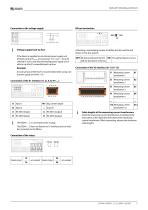
Connection to the voltage supply | u u I J Voltage supply back-up fuse If the device is supplied via an external power supply unit, the back-up fuse Fback-upat connection "A1/+ A2/-” must be selected in such a way that the feeding power supply unit is able to trip the DC-compatible back-up fuse. A back-up fuse of650 mA/Tis recommended when using a 24 Vpower supply unit (min. 1 A). The EDS44...-S does not feature an X1 interface and can only be connected via the BB bus. Activating a terminating resistor to define the first and the last device in the bus system. J Cable lengths of the measuring...
Open the catalog to page 5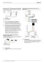
Connection of CTAC… series measuring current transformers For insulation fault location, the measuring current transformers of the CTAC… series are used. Connection of measuring current transformer CTBC… to EDS441-LAB-4 CTAC… series measuring current transformers Terminals 1 and 2 as well as terminals 3 and 4 of the measuring current transformer are bridged internally. The connections k and l must not be interchanged on the EDS44…. Live conductors and measuring current transformers Ensure that all live conductors are routed through the measuring current transformer. Do not route any existing...
Open the catalog to page 6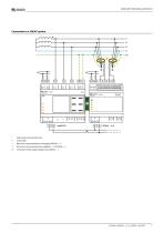
Connection to a 3(N)AC system 1 Measuring current transformers Us Connection of the supply voltage only to EDS44...-L
Open the catalog to page 7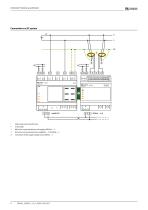
Connection to a DC system 1 Measuring current transformers Us Connection of the supply voltage only to EDS44...-L
Open the catalog to page 8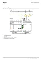
Connection to an AC system 1 Measuring current transformers Us Connection of the supply voltage only to EDS44...-L
Open the catalog to page 9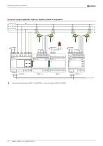
Connection example: ISOMETER® iso685-D-P, EDS440-S, IOM441-S and EDS440-L Communication between iso685-...-P and EDS44...-L runs exclusively via BS bus (RS-485).
Open the catalog to page 10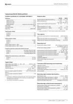
Technical data ISOSCAN® EDS440 and EDS441 Response values Supply circuit (IC1) Output circuit 1 (IC2) Output circuit 2 (IC3) Control circuit (IC4) Rated voltage Overvoltage category Range of use Response value for insulation fault location (/AL) 2.10 mA 0.2.1 mA min. ±2 mA min. ±0.2 mA Response value for residual current measurement 0.1.10 A 0.1.1 A Rated impulse voltage Rated insulation voltage Pollution degree outside (Un < 690 V) 3 Pollution degree outside (Un > 690 V < 1000 V) 2 Protective separation (reinforced insulation) between Voltage tests (routine test) acc. to IEC 61010-1 Supply voltage...
Open the catalog to page 11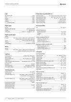
SERVICE yellow 1...12 channel indication yellow Contact data acc. to IEC 60947-5-1 Utilization category AC-13 / AC-14 / DC-12 / DC-12 / DC-12 / DC-12 Rated operational voltage 230 V / 230 V / 24 V / 48 V / 110 V / 220 V Rated operational current 5 A / 3 A / 1 A / 1 A / 0.2 A / 0.1 A Minimum contact rating 11 mA at AC/DC >10 V Digital inputs Number Operating mode, adjustable Voltage level active high, active low none, test, reset low DC -5.5 V, high DC 11.32 V Digital current output Ambient temperatures Operating temperature Current Tolerance Load resistance none, alarm IAL, alarm IAn, device...
Open the catalog to page 12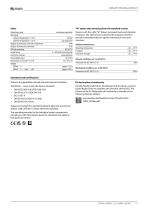
Operating mode Mounting ambient temperature > 55 °C ambient temperature < 55 °C Degree of protection, internal components Degree of protection, terminals DIN rail mounting Screw fixing Enclosure material Flammability class Dimensions in mm (W x H x D) continuous operation vertical any alignment IP40 IP20 IEC 60715 2 x M4 with mounting clip polycarbonate UL 94 V-0 72 x 93 x 63 "W'' option data deviating from the standard version Devices with the suffix "W" feature increased shock and vibration resistance. The electronics is covered with a special varnish to provide increased protection against...
Open the catalog to page 13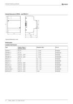
Insulation fault locators
Open the catalog to page 14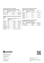
Measuring current transformers for EDS441 Recommended Bender measuring current transformers Measuring current transformers for EDS441-LAB Bender measuring current transformers Alternative measuring current transformers from the Bender program Measuring current transformers for EDS440-LAF Bender measuring current transformers RBENDERBender GmbH & Co. KG Londorfer StraGe 65 35305 Grunberg Germany © Bender GmbH & Co. KG, Germany Subject to change! The specified standards take into account the edition valid until 06.2025 unless otherwise indicated.
Open the catalog to page 16All BENDER GmbH & Co KG catalogs and technical brochures
 CD25000
4 Pages
 CD14400
4 Pages
 CD1000
4 Pages
 AUR381Z
4 Pages
 AN110
AN1104 Pages
 AGH575S-6
4 Pages
 CD1000-2
4 Pages
 MRCDB300 series
12 Pages
 COMTRAXX® COM465IP/COM465DP
10 Pages
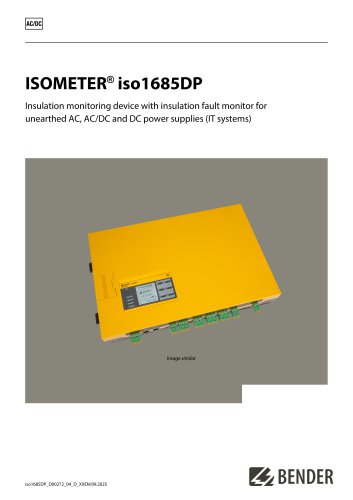 ISOMETER® iso1685DP
10 Pages
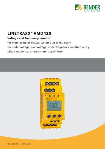 LINETRAXX® VMD420
6 Pages
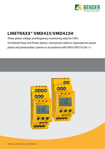 LINETRAXX® VMD423/VMD423H
6 Pages
 ISOMETER® iso685(W)-x-B
12 Pages
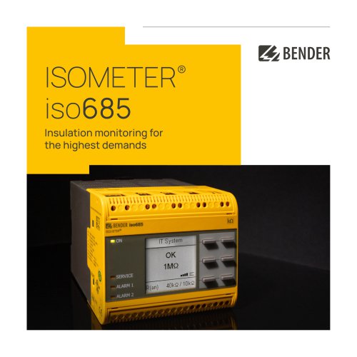 ISOMETER® iso685
12 Pages
 UNIMET® 810ST
4 Pages
 UNIMET® 610ST
4 Pages
 UNIMET® 400ST
4 Pages
 UNIMET® 300ST
4 Pages
 AN111
AN1114 Pages
 AN450
AN4504 Pages
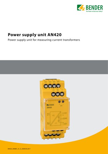 AN420
AN4204 Pages
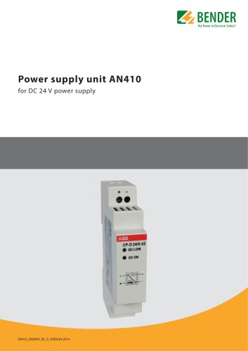 AN410
AN4104 Pages
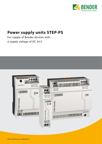 STEP-PS
8 Pages
 CTBC17 series
8 Pages
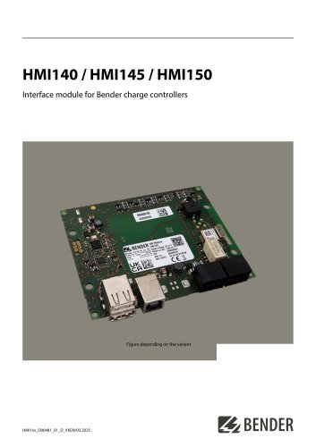 HMI140 / HMI145 / HMI150
6 Pages
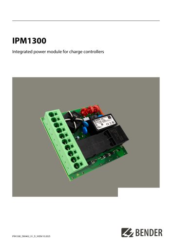 IPM1300
8 Pages
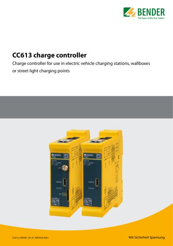 CC613
CC6136 Pages
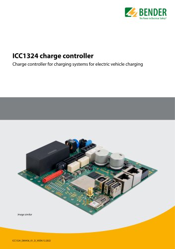 ICC1324
8 Pages
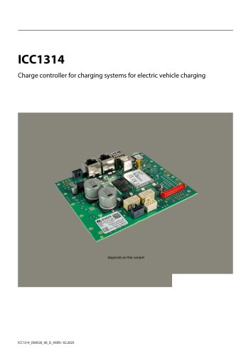 ICC1314
8 Pages
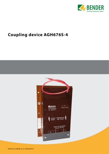 AGH676S-4
4 Pages
 AGH520S
4 Pages
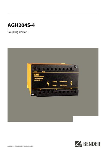 AGH204S-4
4 Pages
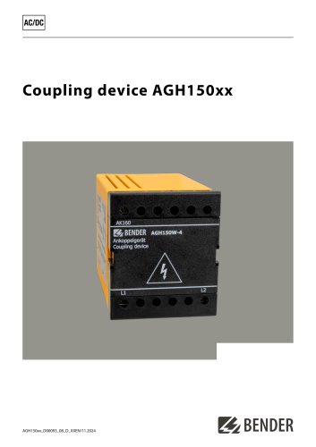 AGH150xx
4 Pages
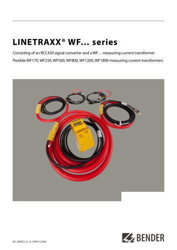 LINETRAXX® WF… series
4 Pages
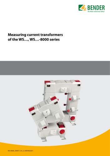 WS…, WS…-8000 series
4 Pages
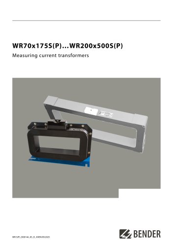 WR70x175S(P)…WR200x500S(P)
4 Pages
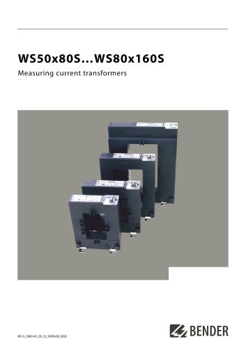 WS50x80S…WS80x160S
4 Pages
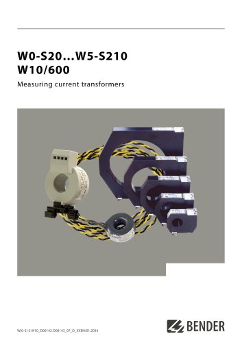 W0-S20…W5-S210 W10/600
4 Pages
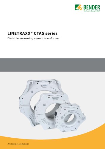 LINETRAXX® CTAS series
8 Pages
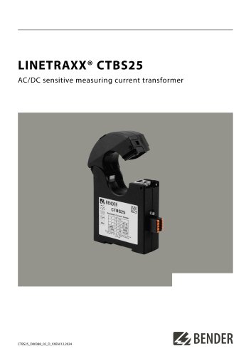 LINETRAXX® CTBS25
4 Pages
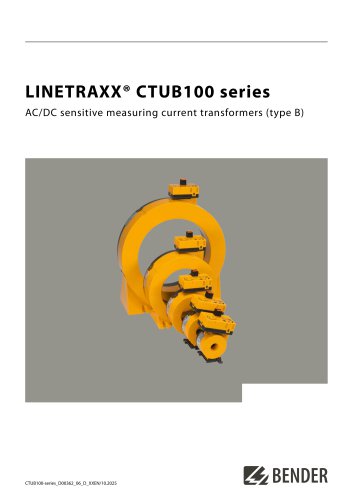 LINETRAXX® CTUB100 series
10 Pages
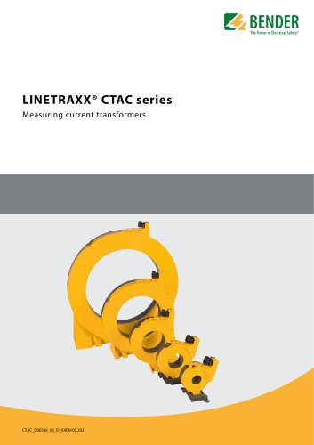 LINETRAXX® CTAC series
6 Pages
 AT series
6 Pages
 COMTRAXX® MK2430
6 Pages
 COMTRAXX® CP305
12 Pages
 COMTRAXX® CP9xx
8 Pages
 DI-1DL
4 Pages
 SMO482P-12
4 Pages
 Signal converter SMI473
4 Pages
 DI-2USB
4 Pages
 COMTRAXX® COM463BC
7 Pages
 COMTRAXX® COM465ID
8 Pages
 COMTRAXX® EDGE500
12 Pages
 COMTRAXX® CP9…-I Series
10 Pages
 POWERSCOUT®
8 Pages
 LINETRAXX® GM420
6 Pages
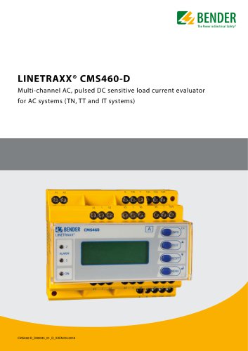 LINETRAXX® CMS460-D
10 Pages
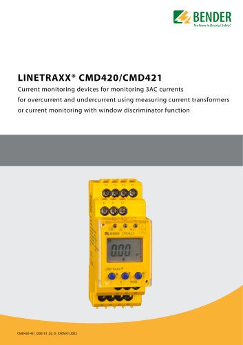 LINETRAXX® CMD420/CMD421
6 Pages
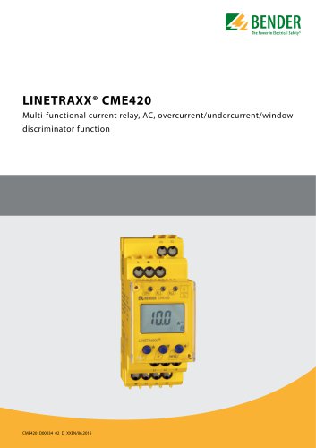 LINETRAXX® CME420
6 Pages
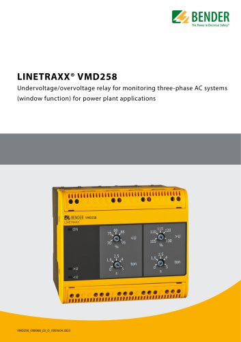 LINETRAXX® VMD258
6 Pages
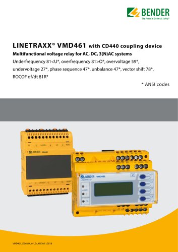 LINETRAXX® VMD461
10 Pages
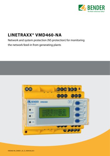 LINETRAXX® VMD460-NA
8 Pages
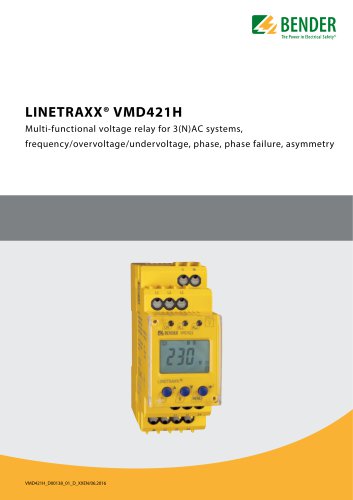 LINETRAXX® VMD421H
6 Pages
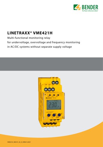 LINETRAXX® VME421H
6 Pages
 LINETRAXX® VME420
6 Pages
 SEB30, SEB60
8 Pages
 UMA710-2-xx-DIO, …-BP
6 Pages
 UMA710-2-…-ISO…
6 Pages
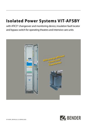 VIT-AFSBY
6 Pages
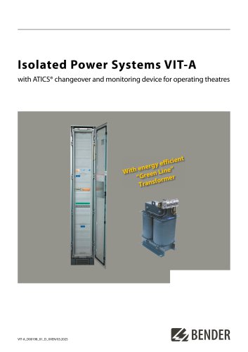 VIT-A
VIT-A6 Pages
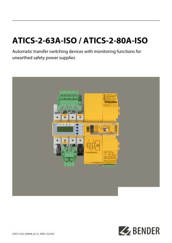
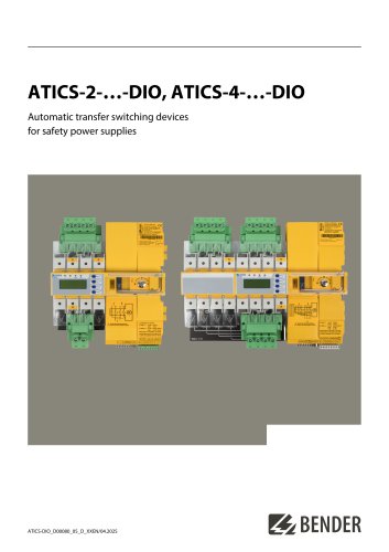 ATICS-2-…-DIO, ATICS-4-…-DIO
8 Pages
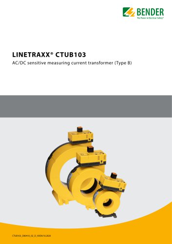 LINETRAXX® CTUB103
6 Pages
 NGRM700 (HRG)/NGRM750 (LRG)
12 Pages
 NGRM500 (HRG)/NGRM550 (LRG)
12 Pages
 RDC125-5S
12 Pages
 RCMB131-01
4 Pages
 RDC121
7 Pages
 RCMB123
7 Pages
 Residual current sensors
2 Pages
 LINETRAXX® RCM420
6 Pages
 LINETRAXX® RCMA420
6 Pages
 LINETRAXX® RCMA423
6 Pages
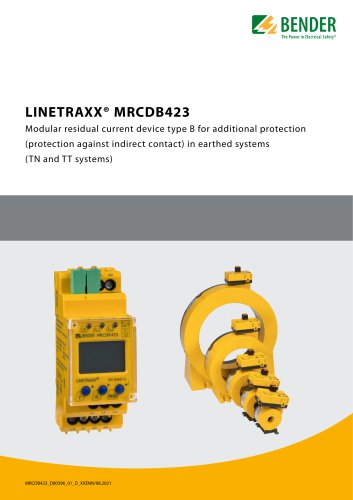 LINETRAXX® MRCDB423
6 Pages
 RDC104-4
6 Pages
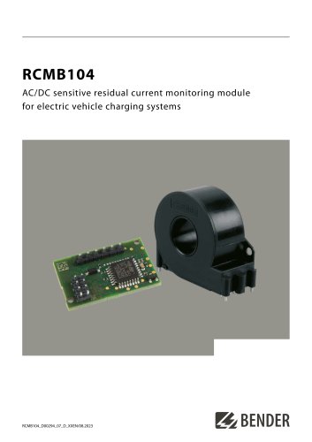
 RCMB104
6 Pages
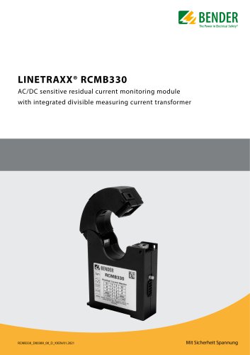 LINETRAXX® RCMB330
4 Pages
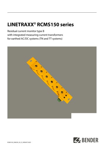 LINETRAXX® RCMS150 series
8 Pages
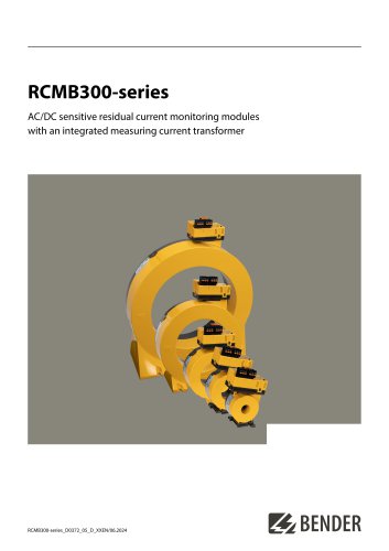 RCMB300-series
12 Pages
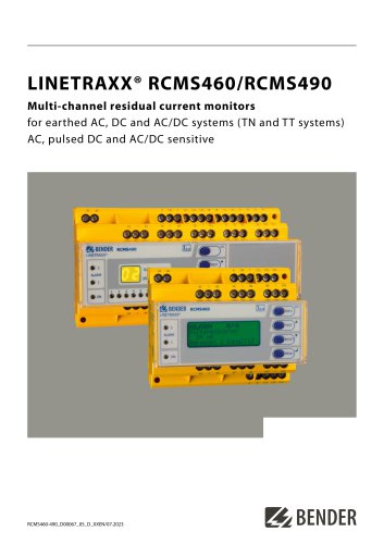 LINETRAXX® RCMS460/RCMS490
14 Pages
 LINETRAXX® SmartDetect RCMS410
10 Pages
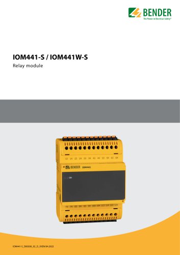 IOM441-S / IOM441W-S
4 Pages
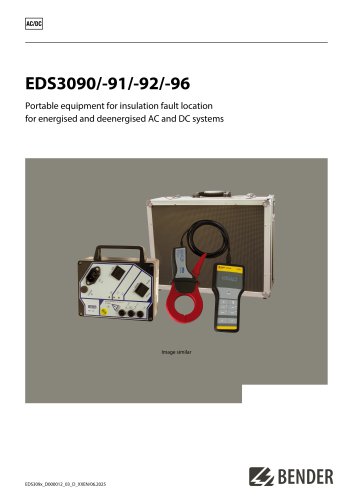 EDS3090/-91/-92/-96
14 Pages
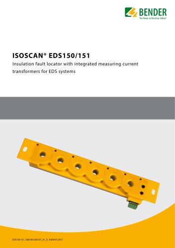 ISOSCAN® EDS150/151
6 Pages
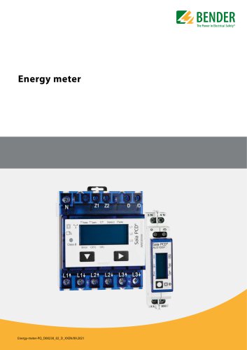 Energy meter
6 Pages
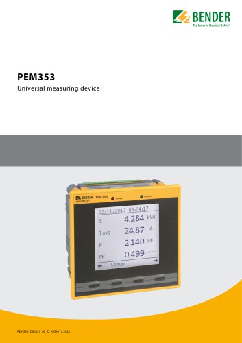 PEM353
8 Pages
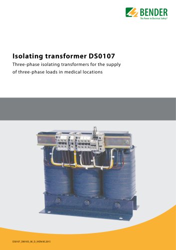 DS0107
6 Pages
 ESL0107
4 Pages
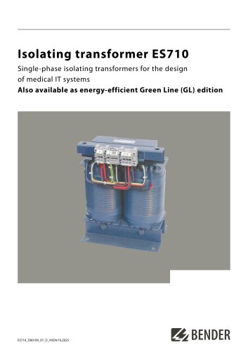 ES710
ES7108 Pages
 7204/7220/9604/9620
4 Pages
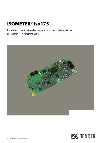 ISOMETER® iso175
8 Pages
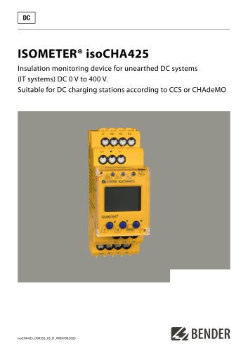 ISOMETER® isoCHA425
8 Pages
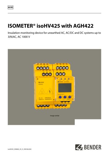 ISOMETER® isoHV425 with AGH422
10 Pages
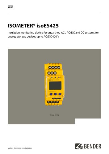 ISOMETER® isoES425
8 Pages
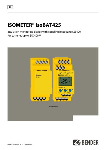 ISOMETER® isoBAT425
8 Pages
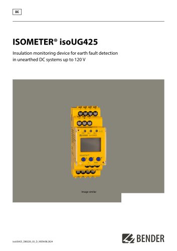 ISOMETER® isoUG425
6 Pages
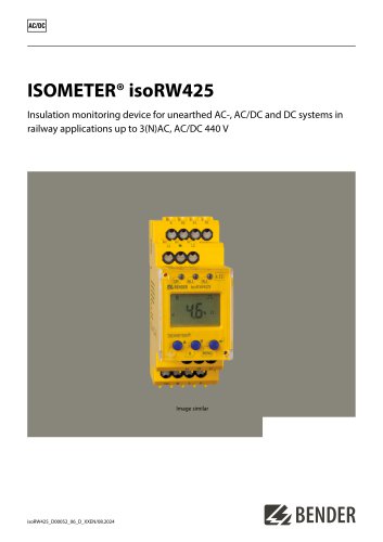 ISOMETER® isoRW425
8 Pages
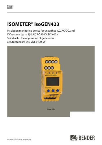 ISOMETER® isoGEN423
6 Pages
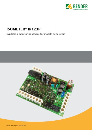 ISOMETER® IR123P
4 Pages
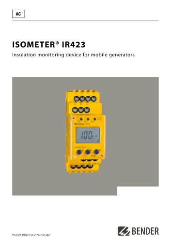 ISOMETER® IR423
6 Pages
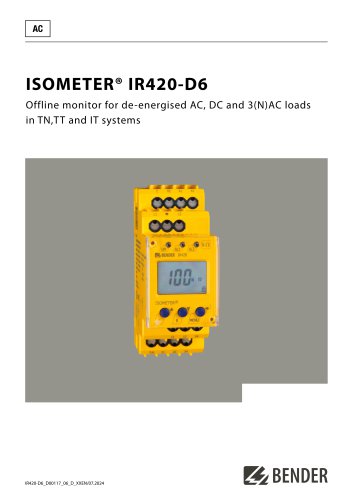 ISOMETER® IR420-D6
6 Pages
 ISOMETER® isoPV1685DP
10 Pages
 ISOMETER® isoPV1685RTU
8 Pages
 ISOMETER® isoPV
8 Pages
 ISOMETER® isoLR275
6 Pages
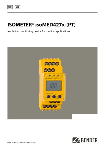 ISOMETER® isoMED427x-(PT)
6 Pages
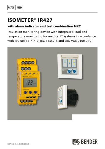 ISOMETER® IR427
8 Pages
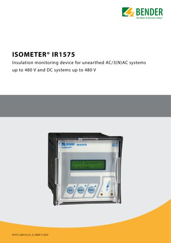 ISOMETER® IR1575
6 Pages
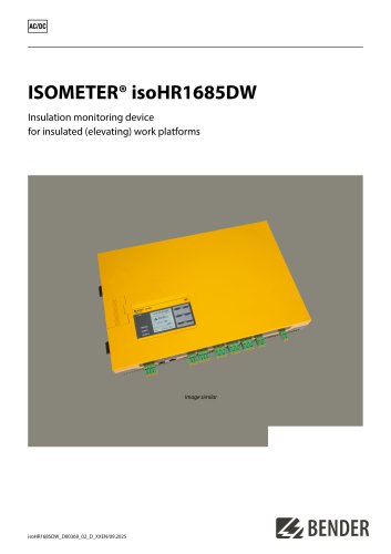 ISOMETER® isoHR1685DW
10 Pages
 ISOMETER® IR425-D4
6 Pages
 ISOMETER® IR420-D4
6 Pages
 ISOMETER® iso415R
2 Pages
 ISOMETER® IRDH275BM-7
6 Pages
 ISOMETER® isoRW685W-D-B
10 Pages
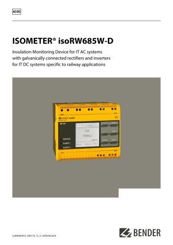 ISOMETER® isoRW685W-D
10 Pages
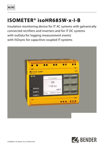 ISOMETER® isoHR685W-x-I-B
10 Pages
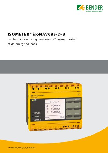 ISOMETER® isoNAV685-D-B
8 Pages
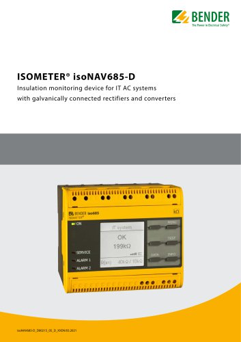 ISOMETER® isoNAV685-D
8 Pages
 AGH520S
4 Pages
 NGRM500 et NGRM550
12 Pages
 RCM410R
8 Pages
 RCMS410
10 Pages
 RCMS425-D
10 Pages
 EDGE500
12 Pages
 Iso415R
4 Pages
 Iso685-x-B
12 Pages
 Iso685-x-P
14 Pages
 Iso685-x
12 Pages
 Data Centers
16 Pages
 RCMB104
6 Pages
 LINETRAXX® RCMS460 / RCMS490
14 Pages
 LINETRAXX® SmartDetect RCMS410
10 Pages
 Main Catalogue
486 Pages
- DC power supply
- Display module
- AC/DC power supply
- Measuring device
- BENDER dry transformer
- CE power supply
- Cloud-based software
- Junction block
- Single-output power supply
- Power supply for industrial applications
- Portable tester
- Monitoring software solution
- Communication gateway
- LED display panel
- BENDER IEC transformer
- Power supply with overload protection
- Compact power supply