
- Catalogs
- BENDER GmbH & Co KG
- ISOMETER® isoNAV685-D


- Company
- Products
- Catalogs
- News & Trends
- Exhibitions
ISOMETER® isoNAV685-D
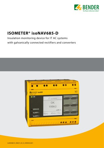
ISOMETER® isoNAV685-D
- Conductor Sizes: Single conductor (0.25–2.5 mm²), Multiple conductor (0.5–1.5 mm²)
- Push-wire Terminals X1: Nominal current ≤ 8 A, Conductor sizes AWG 24-16
- Continuous operation
- Display oriented mounting
- Degree of protection: IP40 (internal), IP20 (terminals)
- DIN rail mounting
- Polycarbonate enclosure
- Flammability class V-0
- Insulation required for X1 connection at frequencies > 200 Hz
- Fast tripping only in 60 Hz IT networks
- Indication limited outside -25 to +55 °C
- Class A product may cause radio interference
- Screw-type terminals set: Art. No. B91067901
- Push-wire terminals set: Art. No. B91067902
- Enclosure accessories: Art. No. B91067903
- Nominal system voltage: AC 0–690 V, DC 0–1000 V
- Supply voltage: AC/DC 24–240 V
- Type: isoNAV685-D, Art. No. B91067014
Catalog excerpts
Insulation monitoring device for IT AC systems with galvanically connected rectifiers and converters data info
Open the catalog to page 1
ISOMETER® isoNAV685-D Insulation monitoring device for IT AC systems with galvanically connected rectifiers and converters Device features • ISOMETER® for IT AC systems with galvanically connected rectifiers or inverters and for IT DC systems • Automatic adaptation to the existing system leakage capacitance • Combination of AMPPus and other profile-dependent measurement methods • An adjustable response value for insulation monitoring in the range of 1 kfi.10 MO (factory setting = 5 kfi) and a response value of 150 V for the DC offset voltage • High-resolution graphic LC display for excellent...
Open the catalog to page 2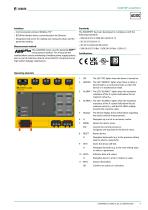
AC/DC Interfaces • Communication protocol Modbus TCP • BCOM for Bender device communication via Ethernet • Integrated web server for reading out measured values and for parameter setting Measurement method The isoNAV685 series uses the patented AMPPlus measurement method. This measurement method allows concise monitoring of modern power supply systems, also in case of extensive, directly connected DC components and high system leakage capacitances. The ISOMETER® has been developed in compliance with the following standards: Operating elements jjoojj jjoojj E& BENDER iso685 DATA INFO 1 - ON The...
Open the catalog to page 3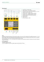
Wiring diagram g*p i 1 - Connection to a 3(N)AC system 2 - Supply voltage Us (see nameplate) via 6 A fuse 3 - Connection to the IT system to be monitored (L1/+, L2, L3/-) 5 - (K1) Alarm relay 1, available changeover contacts 6 - (K2) Alarm relay 2, available changeover contacts 7 - Switchable resistor R for RS-485 bus termination 0 0 on8 7Note: According to DIN VDE 0100-430, devices for protection against a short-circuit can be omitted for the coupling of terminals L1/+, L2, L3/-to the IT system < 690 V to be monitored if the wiring is carried out in such a manner as to reduce the risk of a short-circuit...
Open the catalog to page 4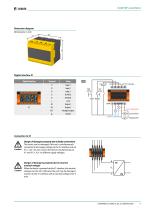
Dimension diagram Dimensions in mm 108 Digital interface X1 Digital interface Input 1 Input 2 Input 3 RS-485 A RS-485 B +24 V Output 1 Output 2 Analogue output Ground Deactivate Device high active TEST RESET +24 V + Q1 Q2 M+ active adjustable passive adjustable Danger of damage to property due to faulty connections! The device can be damaged if the unit is simultaneously connected to the supply voltage via the X1 interface and via A1/+, A2/-. Do not connect the device simultaneously via X1 and A1/+, A2/- to different supply voltages. Danger of damage to property due to incorrect nominal voltage!...
Open the catalog to page 5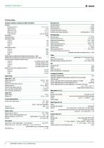
Insulation coordination according to IEC 60664-1/IEC 60664-3 Definitions: Measuring circuit (IC1) Supply circuit (IC2) Output circuit 1 (IC3) Output circuit 2 (IC4) Control circuit (IC5) Rated voltage Overvoltage category Rated impulse voltage: Measuring circuit Measuring current lm Internal resistance R, Zi Permissible extraneous DC voltage Ufg Permissible system leakage capacitance Ce Rated insulation voltage: Pollution degree for accessible parts on the outside of the device housing (Un < 690 V) 3 Pollution degree for accessible parts on the outside of the device housing (Un >690 < 1000 V)...
Open the catalog to page 6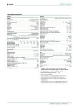
Technical data (continuation) Interfaces Interface/protocol Data rate Max. amount Modbus requests Cable length Network mask BCOM address web server/Modbus TCP/BCOM 10/100 Mbit/s, autodetect DHCP/manual 192.168.0.5 255.255.255.0 system-1-0 communication interface Switching elements Number of switching elements 2 changeover contacts Operating mode N/C operation/N/O operation Contact 11-12-14/21-22-24 none, insulation Alarm 1, insulation fault + DC residual voltage, connection fault, device fault, collective alarm, measurement ended, device inactive Electrical endurance under rated operating conditions,...
Open the catalog to page 7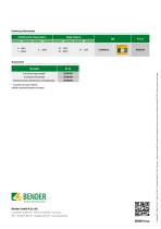
Ordering information Nominal system voltage range Un A set of screw-type terminals1) A set of push-wire terminals Enclosure accessories (terminal cover, 2 mounting clips) 1) included in the scope of delivery Suitable measuring instruments on request! Bender GmbH & Co. KG Londorfer Straße 65 • 35305 Grünberg • Germany Tel.: +49 6401 807-0 • [email protected] • www.bender.de BENDER Group isoNAV685-D_D00215_05_D_XXEN / 03.2021 / © Bender GmbH & Co. KG, Germany – Subject to change! The specified standards take into account the edition valid until 03.2021 unless otherwise i
Open the catalog to page 8All BENDER GmbH & Co KG catalogs and technical brochures
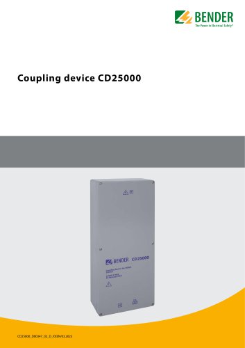 CD25000
4 Pages
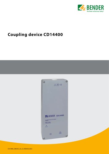 CD14400
4 Pages
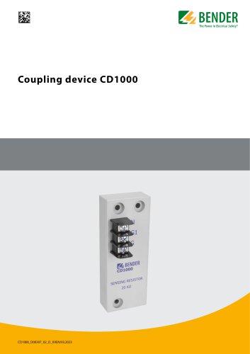 CD1000
4 Pages
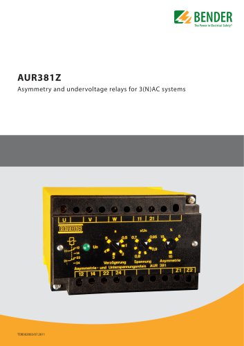 AUR381Z
4 Pages
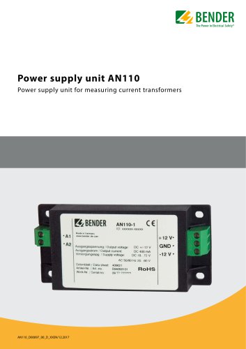 AN110
AN1104 Pages
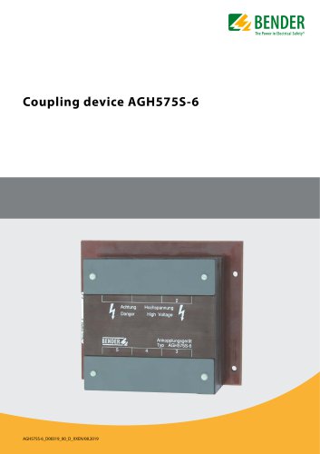 AGH575S-6
4 Pages
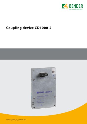 CD1000-2
4 Pages
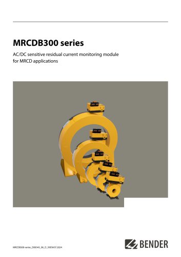 MRCDB300 series
12 Pages
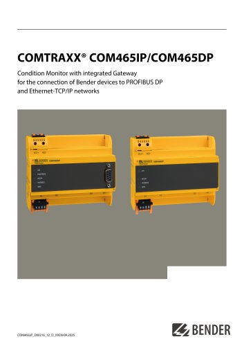 COMTRAXX® COM465IP/COM465DP
10 Pages
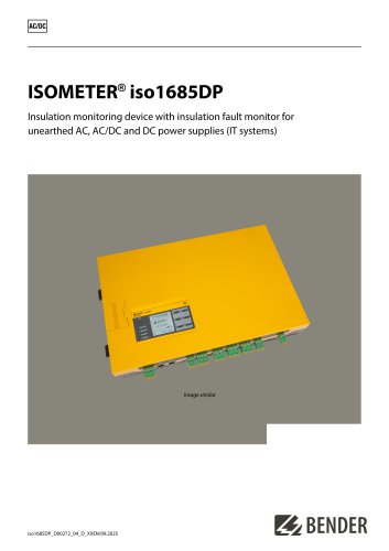 ISOMETER® iso1685DP
10 Pages
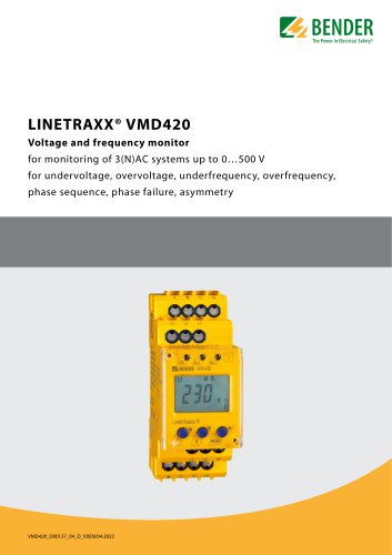 LINETRAXX® VMD420
6 Pages
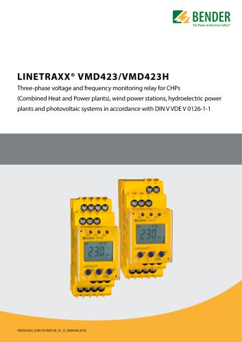 LINETRAXX® VMD423/VMD423H
6 Pages
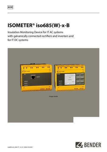
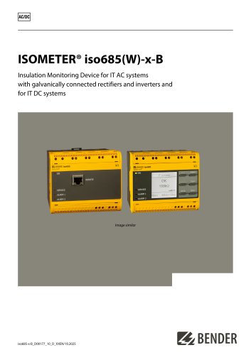 ISOMETER® iso685(W)-x-B
12 Pages
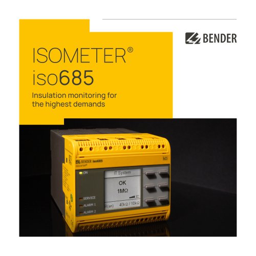 ISOMETER® iso685
12 Pages
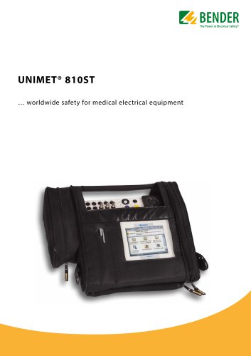 UNIMET® 810ST
4 Pages
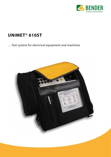 UNIMET® 610ST
4 Pages
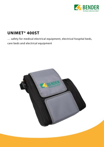 UNIMET® 400ST
4 Pages
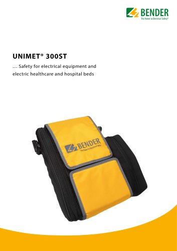 UNIMET® 300ST
4 Pages
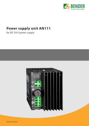 AN111
AN1114 Pages
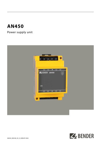 AN450
AN4504 Pages
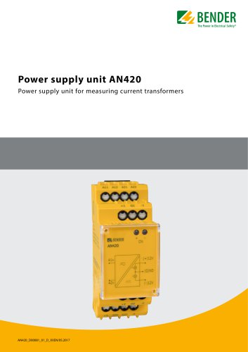 AN420
AN4204 Pages
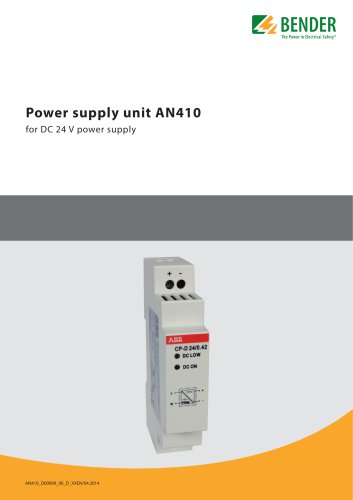 AN410
AN4104 Pages
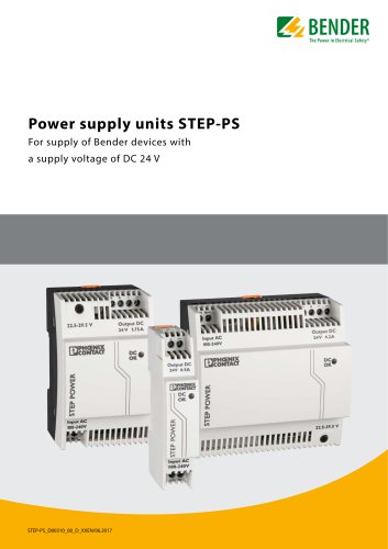 STEP-PS
8 Pages
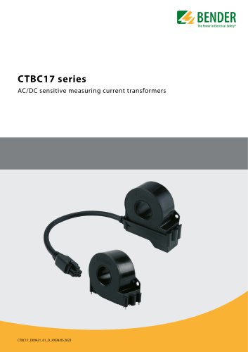 CTBC17 series
8 Pages
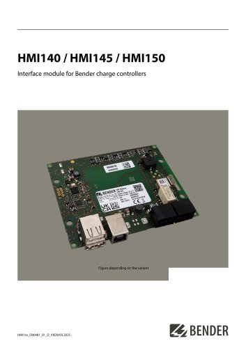 HMI140 / HMI145 / HMI150
6 Pages
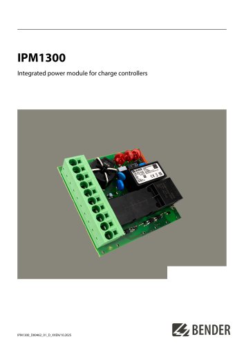 IPM1300
8 Pages
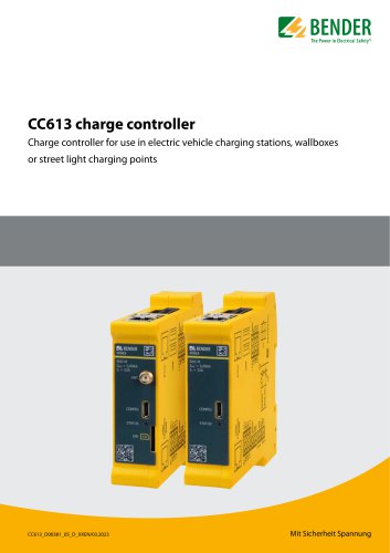 CC613
CC6136 Pages
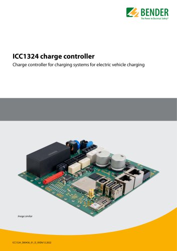 ICC1324
8 Pages
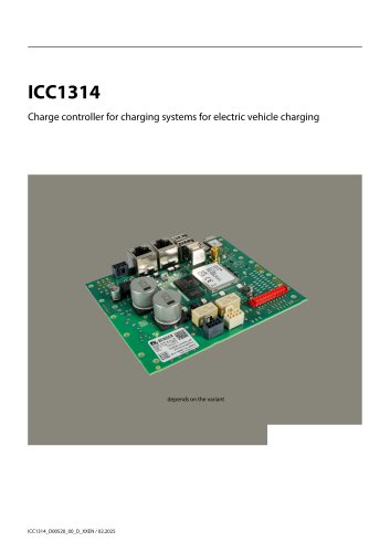 ICC1314
8 Pages
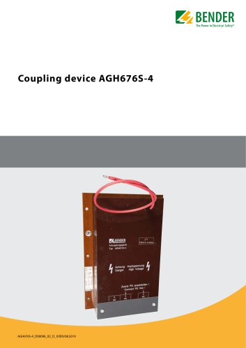 AGH676S-4
4 Pages
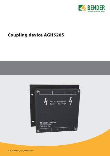 AGH520S
4 Pages
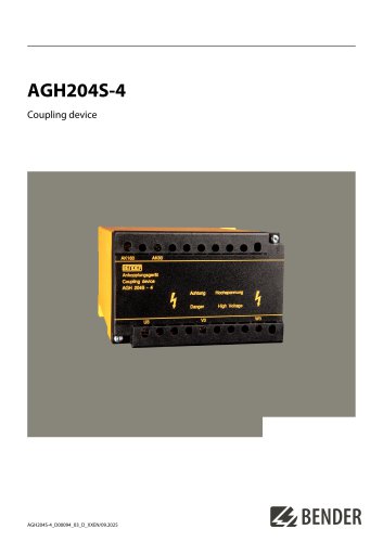 AGH204S-4
4 Pages
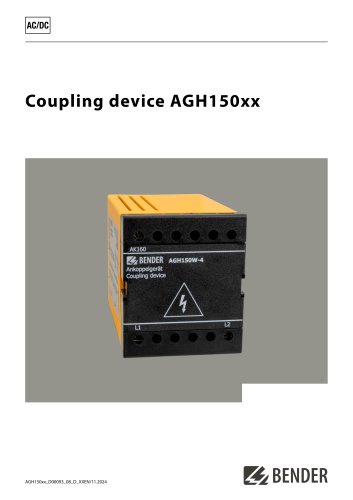 AGH150xx
4 Pages
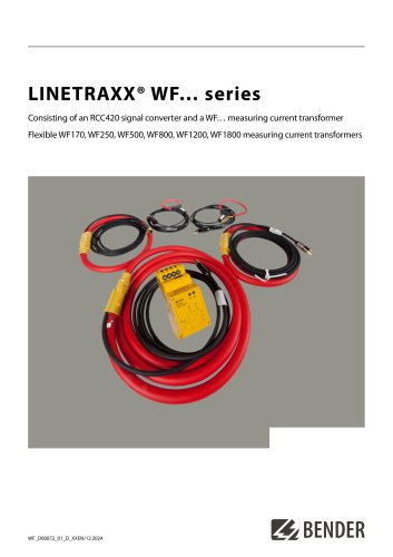 LINETRAXX® WF… series
4 Pages
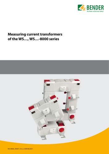 WS…, WS…-8000 series
4 Pages
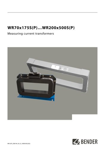 WR70x175S(P)…WR200x500S(P)
4 Pages
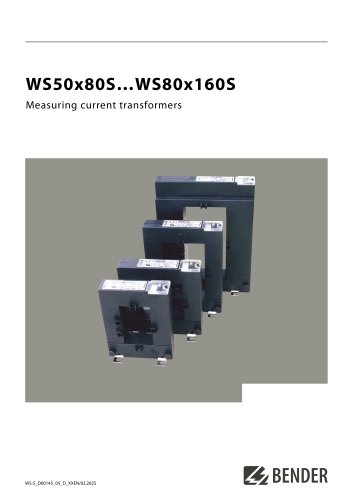 WS50x80S…WS80x160S
4 Pages
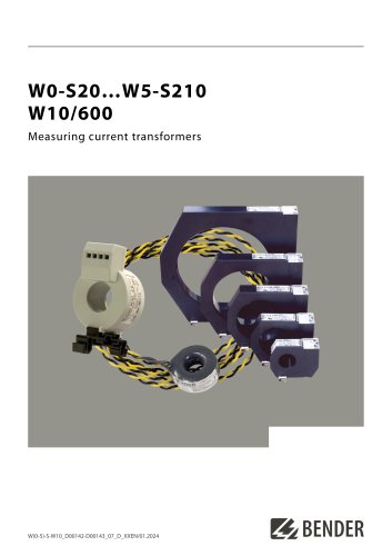 W0-S20…W5-S210 W10/600
4 Pages
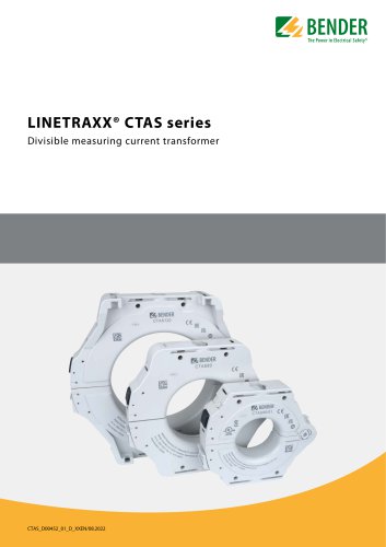 LINETRAXX® CTAS series
8 Pages
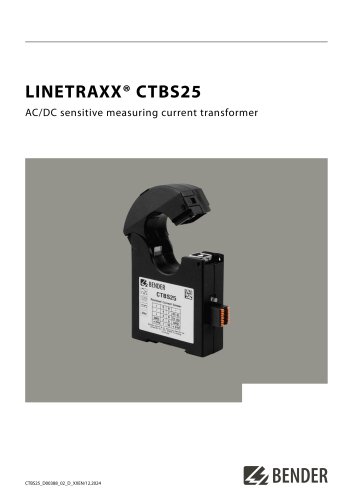 LINETRAXX® CTBS25
4 Pages
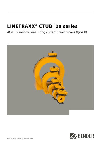 LINETRAXX® CTUB100 series
10 Pages
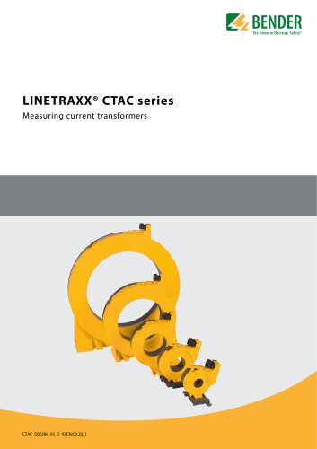 LINETRAXX® CTAC series
6 Pages
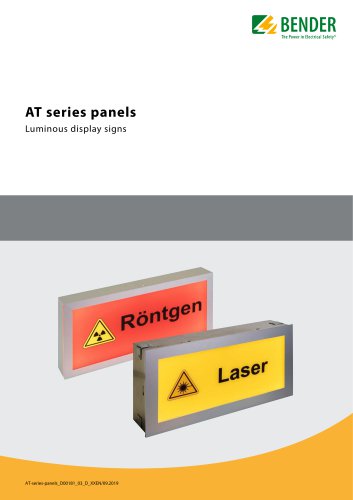 AT series
6 Pages
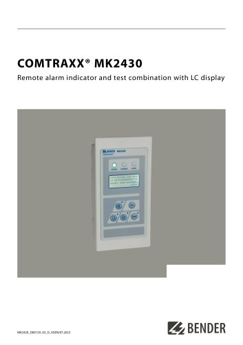 COMTRAXX® MK2430
6 Pages
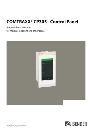 COMTRAXX® CP305
12 Pages
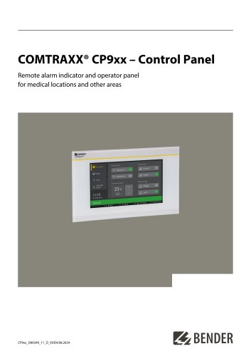 COMTRAXX® CP9xx
8 Pages
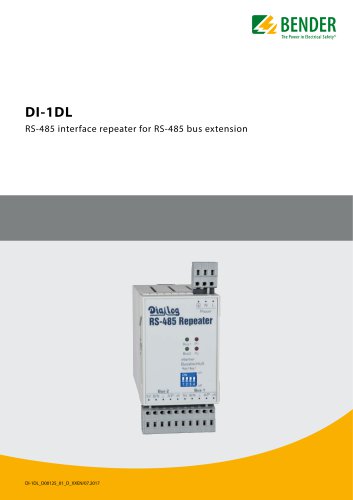 DI-1DL
4 Pages
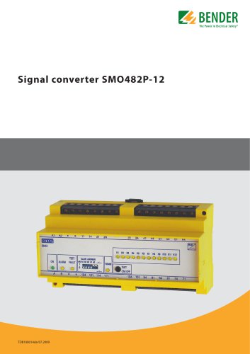 SMO482P-12
4 Pages
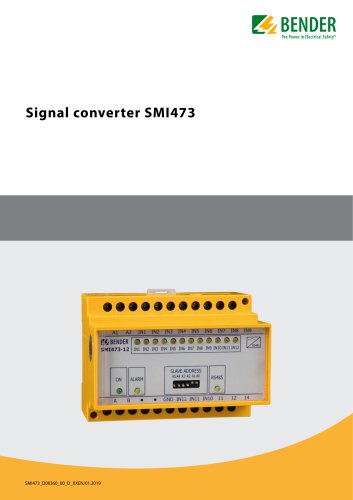 Signal converter SMI473
4 Pages
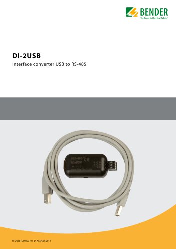 DI-2USB
4 Pages
 COMTRAXX® COM463BC
7 Pages
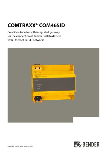 COMTRAXX® COM465ID
8 Pages
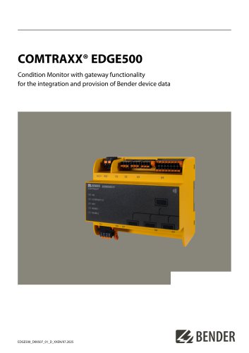
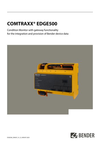 COMTRAXX® EDGE500
12 Pages
 COMTRAXX® CP9…-I Series
10 Pages
 POWERSCOUT®
8 Pages
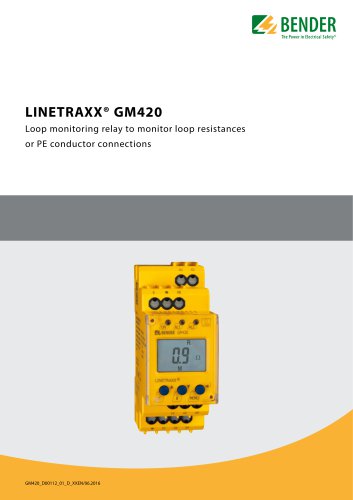 LINETRAXX® GM420
6 Pages
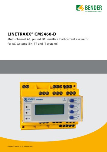 LINETRAXX® CMS460-D
10 Pages
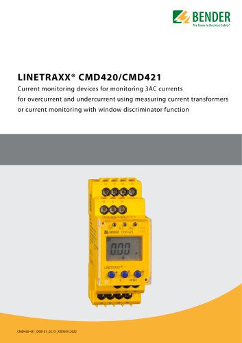 LINETRAXX® CMD420/CMD421
6 Pages
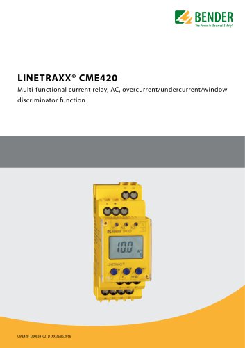 LINETRAXX® CME420
6 Pages
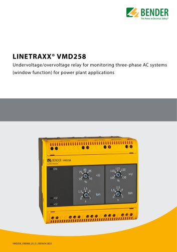 LINETRAXX® VMD258
6 Pages
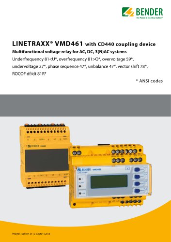 LINETRAXX® VMD461
10 Pages
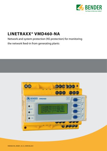 LINETRAXX® VMD460-NA
8 Pages
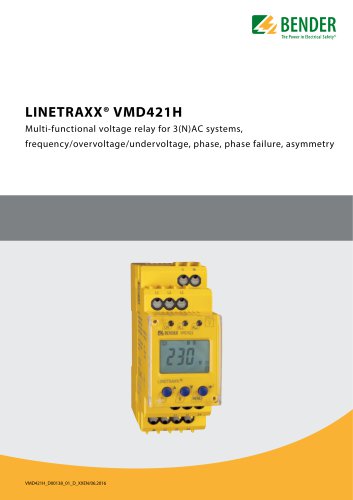 LINETRAXX® VMD421H
6 Pages
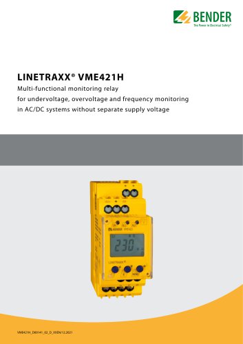 LINETRAXX® VME421H
6 Pages
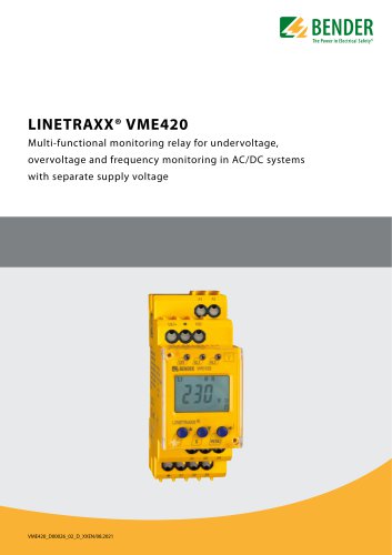 LINETRAXX® VME420
6 Pages
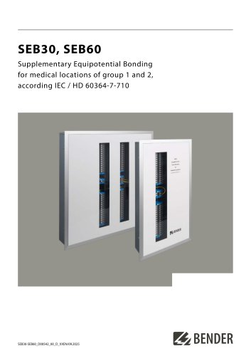 SEB30, SEB60
8 Pages
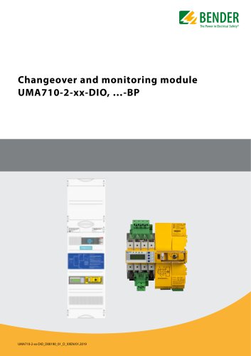 UMA710-2-xx-DIO, …-BP
6 Pages
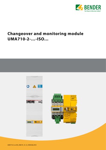 UMA710-2-…-ISO…
6 Pages
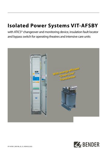 VIT-AFSBY
6 Pages
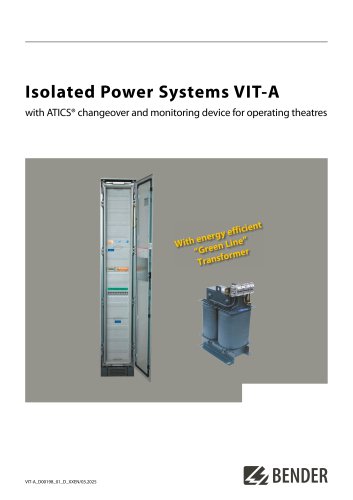 VIT-A
VIT-A6 Pages
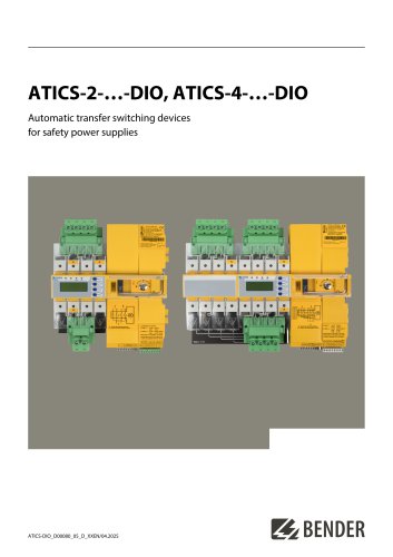 ATICS-2-…-DIO, ATICS-4-…-DIO
8 Pages
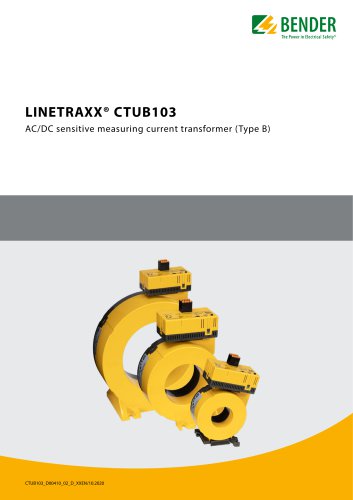 LINETRAXX® CTUB103
6 Pages
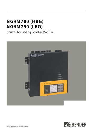 NGRM700 (HRG)/NGRM750 (LRG)
12 Pages
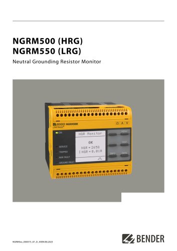 NGRM500 (HRG)/NGRM550 (LRG)
12 Pages
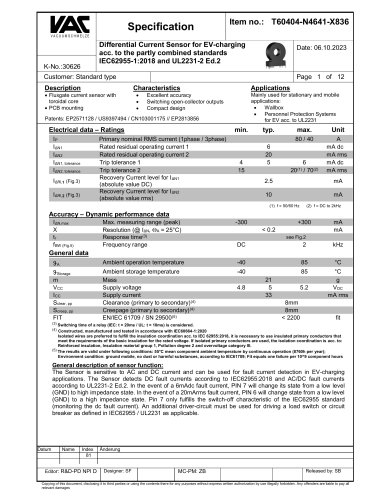 RDC125-5S
12 Pages
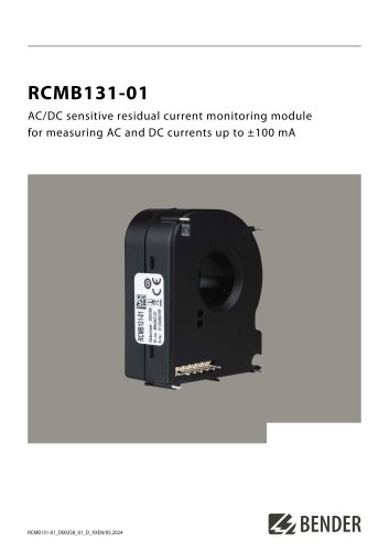 RCMB131-01
4 Pages
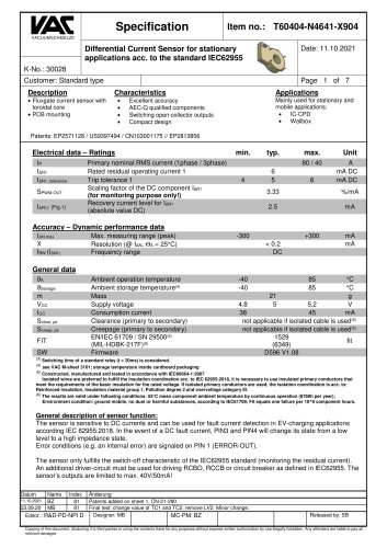 RDC121
7 Pages
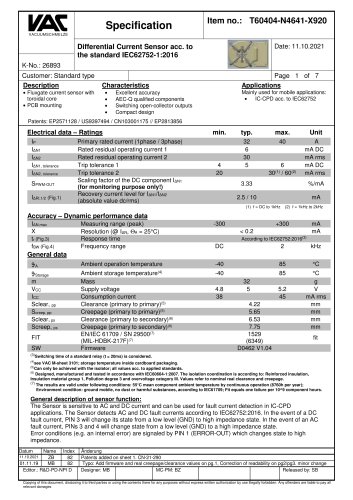 RCMB123
7 Pages
 Residual current sensors
2 Pages
 LINETRAXX® RCM420
6 Pages
 LINETRAXX® RCMA420
6 Pages
 LINETRAXX® RCMA423
6 Pages
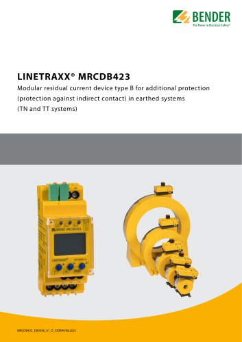 LINETRAXX® MRCDB423
6 Pages
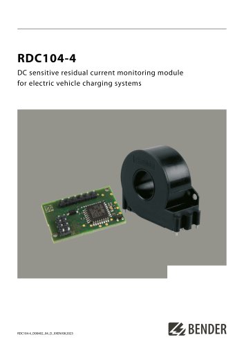 RDC104-4
6 Pages
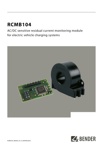 RCMB104
6 Pages
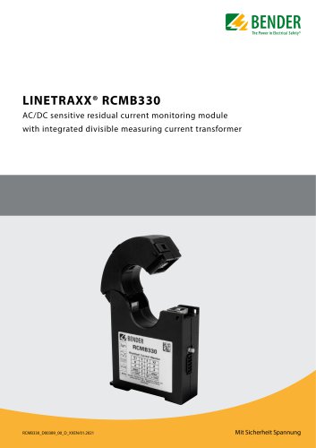 LINETRAXX® RCMB330
4 Pages
 LINETRAXX® RCMS150 series
8 Pages
 RCMB300-series
12 Pages
 LINETRAXX® RCMS460/RCMS490
14 Pages
 LINETRAXX® SmartDetect RCMS410
10 Pages
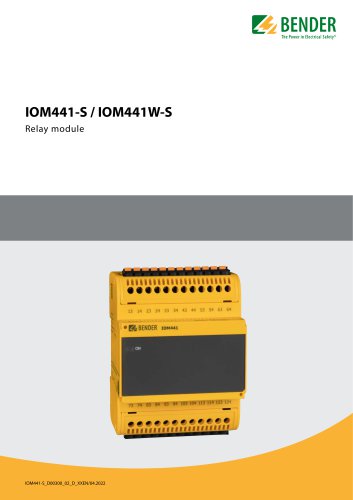 IOM441-S / IOM441W-S
4 Pages
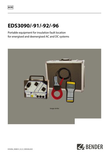 EDS3090/-91/-92/-96
14 Pages
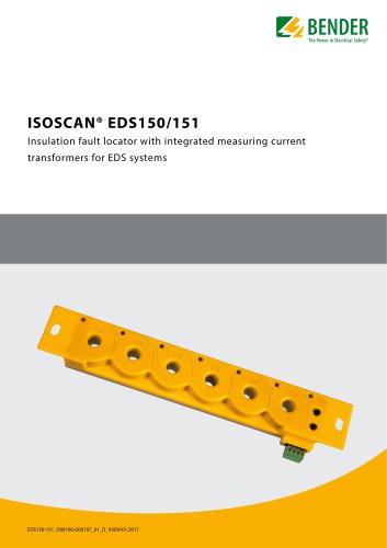 ISOSCAN® EDS150/151
6 Pages
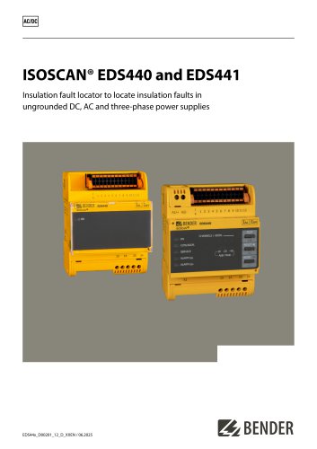 ISOSCAN® EDS440/EDS441
16 Pages
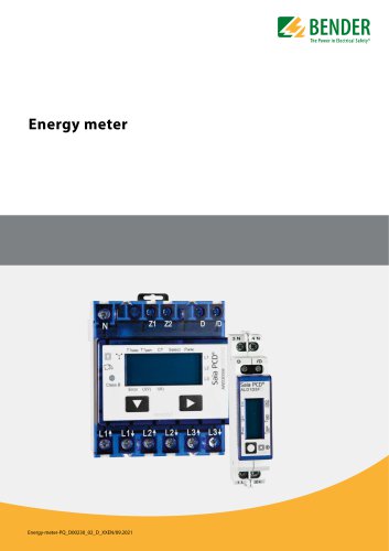 Energy meter
6 Pages
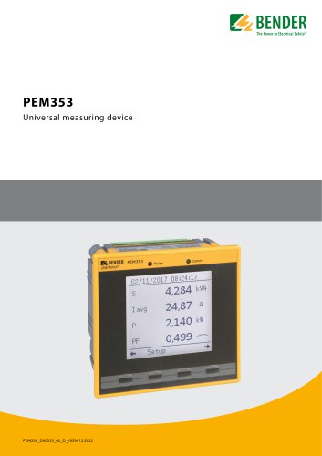 PEM353
8 Pages
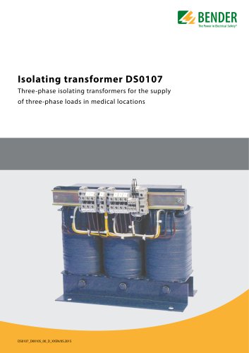 DS0107
6 Pages
 ESL0107
4 Pages
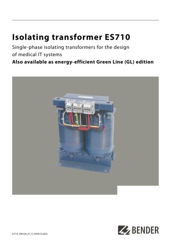 ES710
ES7108 Pages
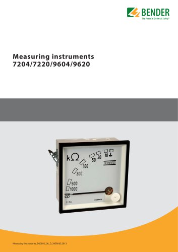 7204/7220/9604/9620
4 Pages
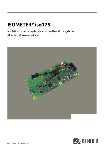 ISOMETER® iso175
8 Pages
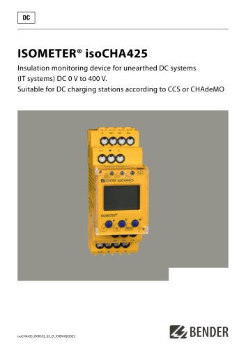 ISOMETER® isoCHA425
8 Pages
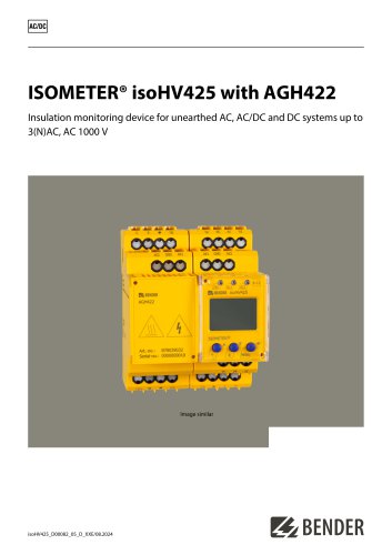 ISOMETER® isoHV425 with AGH422
10 Pages
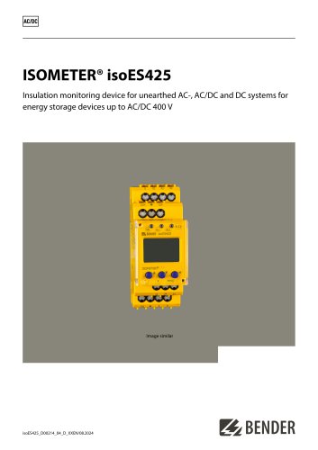 ISOMETER® isoES425
8 Pages
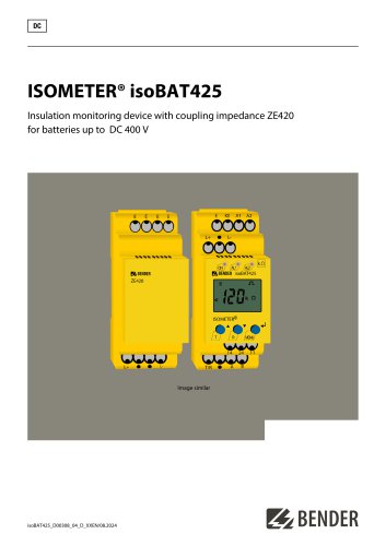 ISOMETER® isoBAT425
8 Pages
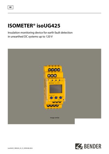 ISOMETER® isoUG425
6 Pages
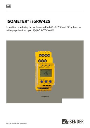 ISOMETER® isoRW425
8 Pages
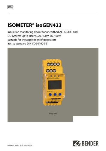 ISOMETER® isoGEN423
6 Pages
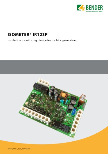 ISOMETER® IR123P
4 Pages
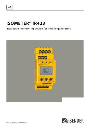 ISOMETER® IR423
6 Pages
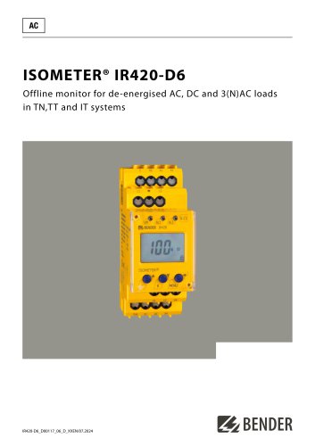 ISOMETER® IR420-D6
6 Pages
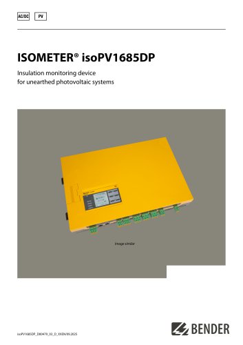 ISOMETER® isoPV1685DP
10 Pages
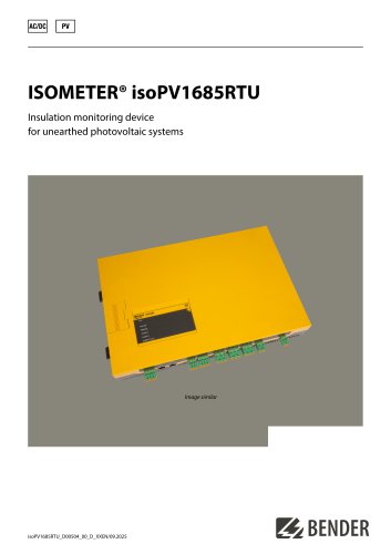 ISOMETER® isoPV1685RTU
8 Pages
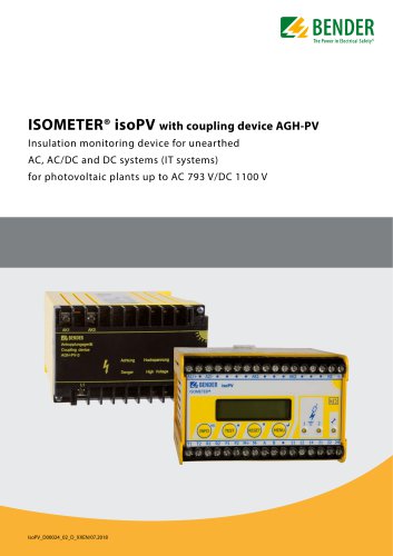 ISOMETER® isoPV
8 Pages
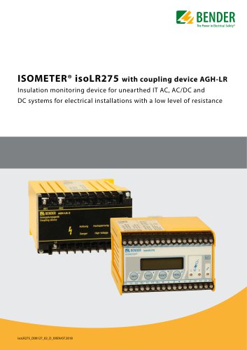 ISOMETER® isoLR275
6 Pages
 ISOMETER® isoMED427x-(PT)
6 Pages
 ISOMETER® IR427
8 Pages
 ISOMETER® IR1575
6 Pages
 ISOMETER® isoHR1685DW
10 Pages
 ISOMETER® IR425-D4
6 Pages
 ISOMETER® IR420-D4
6 Pages
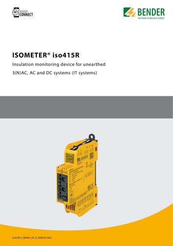
 ISOMETER® iso415R
2 Pages
 ISOMETER® IRDH275BM-7
6 Pages
 ISOMETER® isoRW685W-D-B
10 Pages
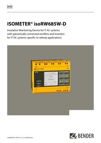 ISOMETER® isoRW685W-D
10 Pages
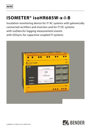 ISOMETER® isoHR685W-x-I-B
10 Pages
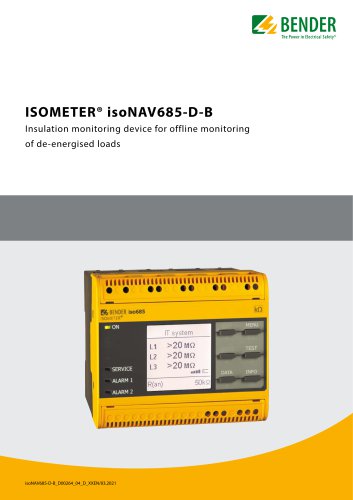 ISOMETER® isoNAV685-D-B
8 Pages
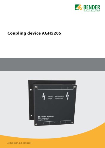 AGH520S
4 Pages
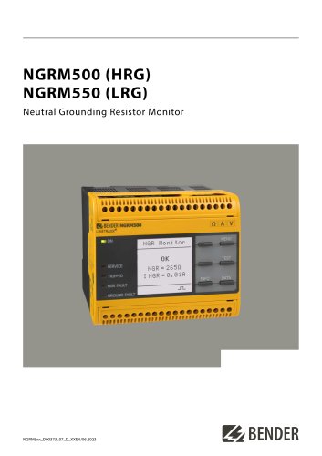 NGRM500 et NGRM550
12 Pages
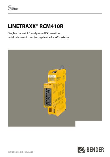 RCM410R
8 Pages
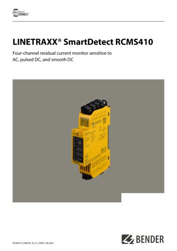 RCMS410
10 Pages
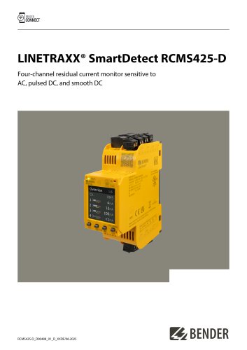 RCMS425-D
10 Pages
 EDGE500
12 Pages
 Iso415R
4 Pages
 Iso685-x-B
12 Pages
 Iso685-x-P
14 Pages
 Iso685-x
12 Pages
 Data Centers
16 Pages
 RCMB104
6 Pages
 LINETRAXX® RCMS460 / RCMS490
14 Pages
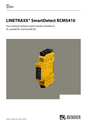 LINETRAXX® SmartDetect RCMS410
10 Pages
 Main Catalogue
486 Pages
- DC power supply
- AC/DC power supply
- BENDER transformer
- BENDER dry transformer
- Junction block
- CE power supply
- Cloud-based software
- Single-output power supply
- Portable tester
- Power supply for industrial applications
- Monitoring software solution
- Communication gateway
- LED display panel
- BENDER IEC transformer
- BENDER current transformer
- Compact power supply
- Automatic tester