
- Catalogs
- BENDER GmbH & Co KG
- ISOMETER® IR420-D4


- Company
- Products
- Catalogs
- News & Trends
- Exhibitions
ISOMETER® IR420-D4
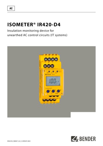
ISOMETER® IR420-D4
- Monitors insulation resistance for unearthed AC control circuits (0-300 V).
- Two adjustable response values with preset function for automatic parameter setting.
- Includes connection monitoring, LEDs for power and alarms, and test/reset buttons.
- Equipped with two alarm relays, selectable N/O or N/C operation, and fault memory.
- Features a multi-functional LC display and adjustable response delay.
- Complies with RoHS standards and uses push-wire terminals.
The ISOMETER® IR420 is designed to monitor insulation resistance in unearthed AC control circuits, particularly in industrial and mechanical engineering applications. It can also monitor de-energised systems using an external supply voltage.
Application- Suitable for AC control circuits in industrial sectors, power plants, elevators, and automation systems.
- Complies with standards such as DIN EN 60204-1 and DIN VDE 0100-725.
The device displays the current insulation resistance and triggers alarms if resistance falls below preset values. It features two alarm relays for prewarning and alarm distinction. Fault memory retains alarm state until reset.
Connection MonitoringAutomatically checks connections every 24 hours or upon pressing the test button. Displays error codes for connection faults.
Preset FunctionAutomatically sets response values based on measured nominal system voltage upon initial connection.
Measurement MethodUses superimposed DC voltage for measurement.
StandardsComplies with DIN EN 61557-8, EN 61557-8, IEC 61557-8, and ASTM F 1207M-96 (2007).
Technical Data- Rated insulation voltage: 250 V, impulse voltage: 4 kV.
- Supply voltage options: AC 16-72 V/DC 9.6-94 V or AC/DC 70-300 V.
- Response values adjustable between 1-200 kΩ.
- Operating temperature range: -25 to +55 °C.
- Connection types include screw-type and push-wire terminals.
Available in two models with different supply voltage ranges and terminal types.
Catalog excerpts
insulation monitoring device for unearthed AC control circuits (IT systems)
Open the catalog to page 1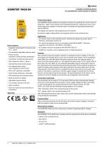
ISOMETER® IR420-D4 Insulation monitoring device for unearthed AC control circuits (IT systems) Device features • Insulation monitoring for IT control circuits AC 0...300 V • Two separately adjustable response values • Preset function (automatic setting of basic parameters) • Connection monitoring system/earth • LEDs: Power On, Alarm 1, Alarm 2 • Internal/external test/reset button • Two separate alarm relays (one changeover contact each) • Fault memory behaviour, selectable • Self monitoring with automatic alarm • Adjustable response delay • RoHS compliant • Push-wire terminal (two terminals...
Open the catalog to page 2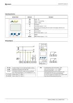
Operating elements Device front Wiring diagram
Open the catalog to page 3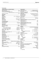
Technical data Rated insulation voltage 250 V Rated impulse voltage/pollution degree 4 kV/3 Protective separation (reinforced insulation) between Supply voltage Supply voltage Us Frequency range Us IR420-D4-2: Supply voltage Us Frequency range Us Power consumption Switching elements Number of switching elements Operating principle Electrical service life, number of cycles Contact data acc. to IEC 60947-5-1 Utilisation category Rated operational voltage Rated operational current Minimum contact rating 2 (changeover contact K1, K2) N/C / N/O operation (N/O operation)* 10000 IT system being monitored...
Open the catalog to page 4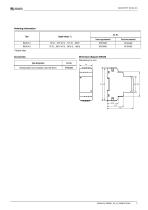
Ordering information
Open the catalog to page 5
Bender GmbH & Co. KG Londorfer Straße 65 35305 Grünberg Germany Tel.: +49 6401 807-0 [email protected] www.bender.de © Bender GmbH & Co. KG, Germany Subject to change! The specified standards take into account the edition valid until 07.2024 unless otherwise indicated.
Open the catalog to page 6All BENDER GmbH & Co KG catalogs and technical brochures
 CD25000
4 Pages
 CD14400
4 Pages
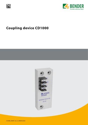 CD1000
4 Pages
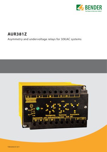 AUR381Z
4 Pages
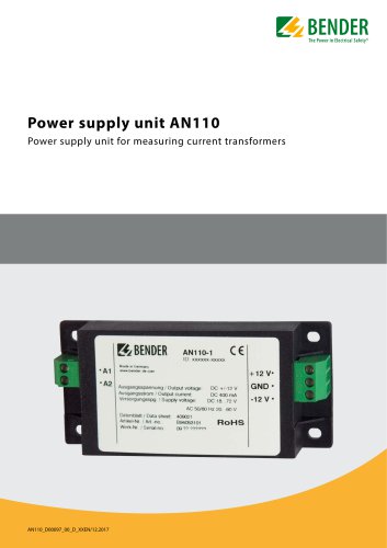 AN110
AN1104 Pages
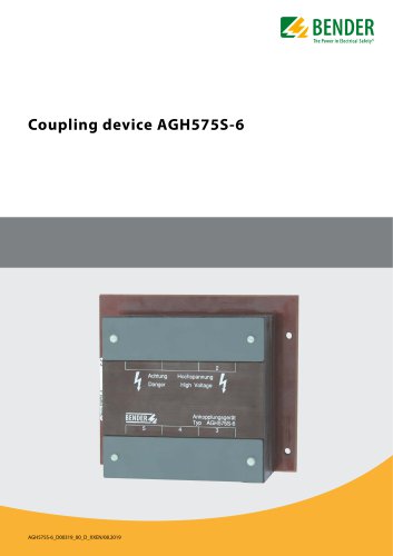 AGH575S-6
4 Pages
 CD1000-2
4 Pages
 MRCDB300 series
12 Pages
 COMTRAXX® COM465IP/COM465DP
10 Pages
 ISOMETER® iso1685DP
10 Pages
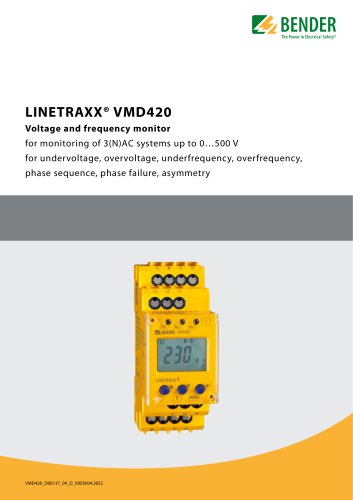 LINETRAXX® VMD420
6 Pages
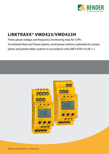 LINETRAXX® VMD423/VMD423H
6 Pages
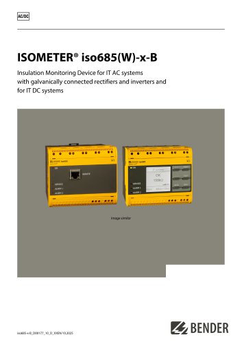 ISOMETER® iso685(W)-x-B
12 Pages
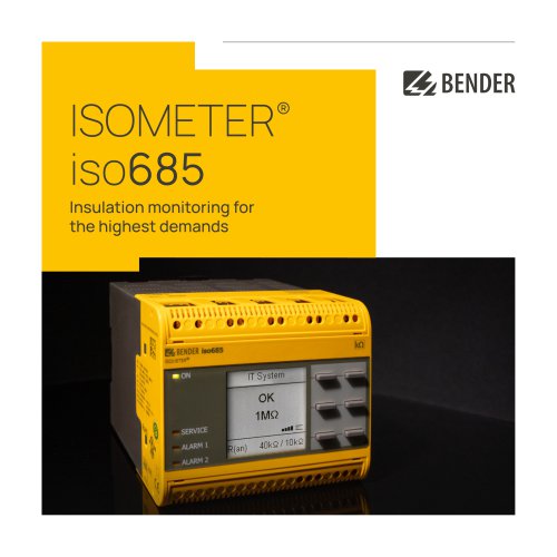 ISOMETER® iso685
12 Pages
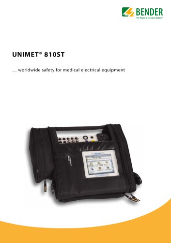 UNIMET® 810ST
4 Pages
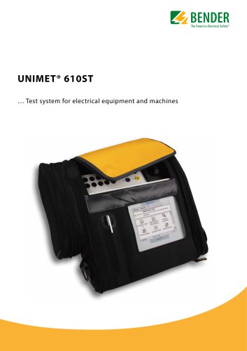 UNIMET® 610ST
4 Pages
 UNIMET® 400ST
4 Pages
 UNIMET® 300ST
4 Pages
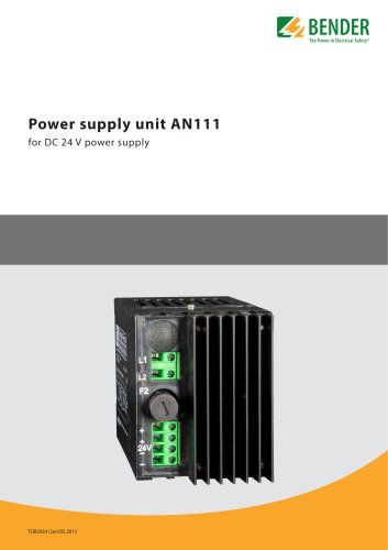 AN111
AN1114 Pages
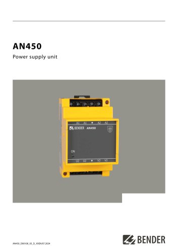 AN450
AN4504 Pages
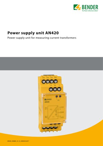 AN420
AN4204 Pages
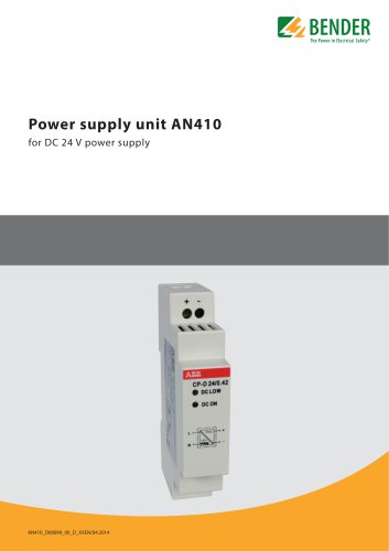 AN410
AN4104 Pages
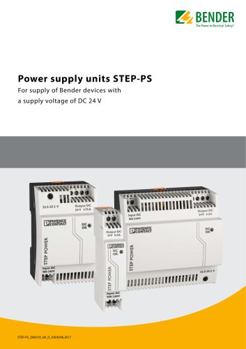 STEP-PS
8 Pages
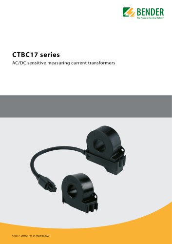 CTBC17 series
8 Pages
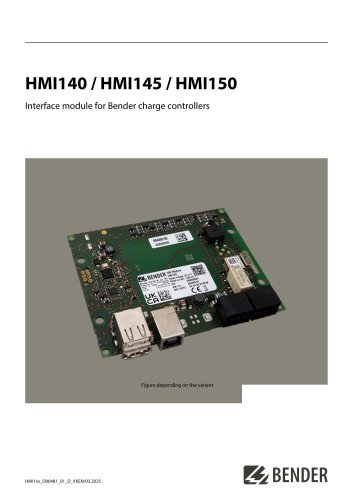 HMI140 / HMI145 / HMI150
6 Pages
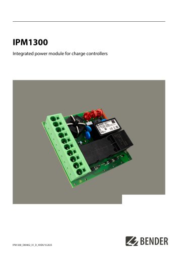 IPM1300
8 Pages
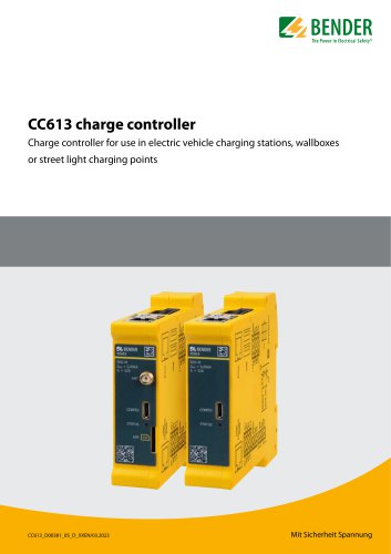 CC613
CC6136 Pages
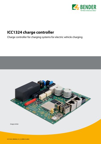 ICC1324
8 Pages
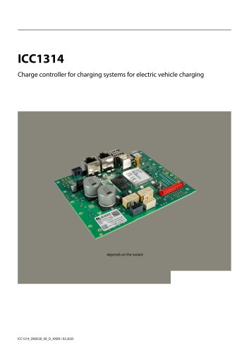 ICC1314
8 Pages
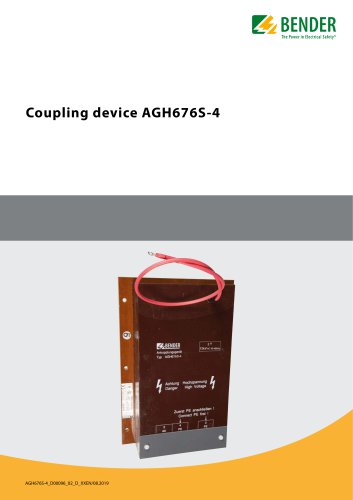 AGH676S-4
4 Pages
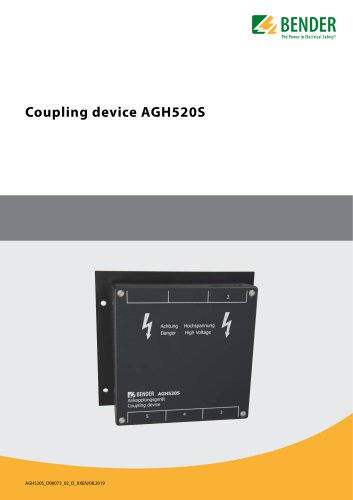 AGH520S
4 Pages
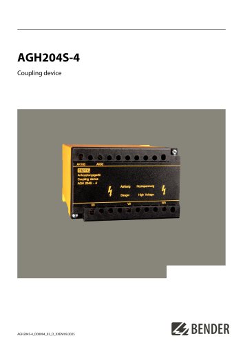 AGH204S-4
4 Pages
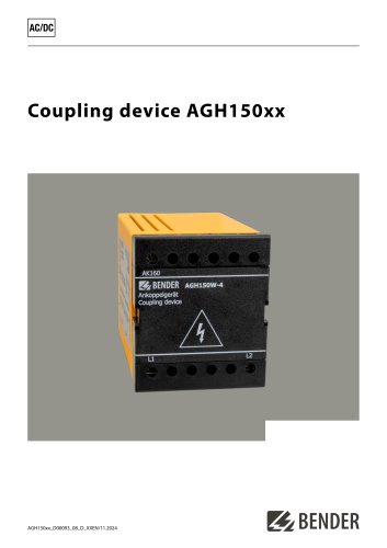 AGH150xx
4 Pages
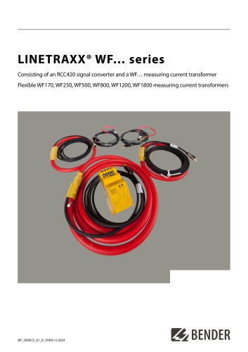 LINETRAXX® WF… series
4 Pages
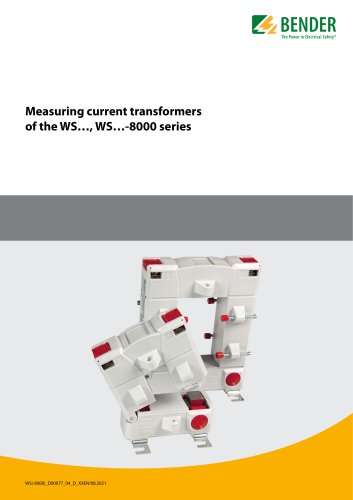 WS…, WS…-8000 series
4 Pages
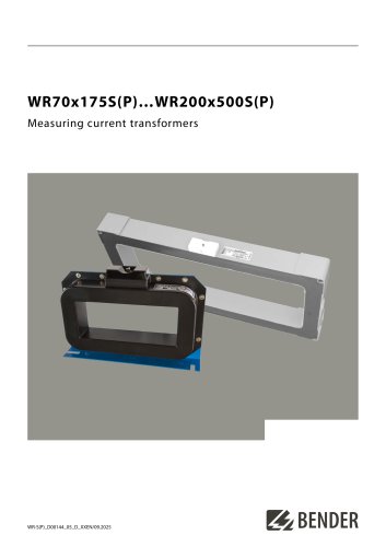 WR70x175S(P)…WR200x500S(P)
4 Pages
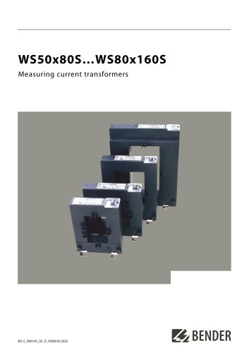 WS50x80S…WS80x160S
4 Pages
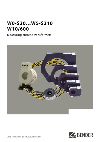 W0-S20…W5-S210 W10/600
4 Pages
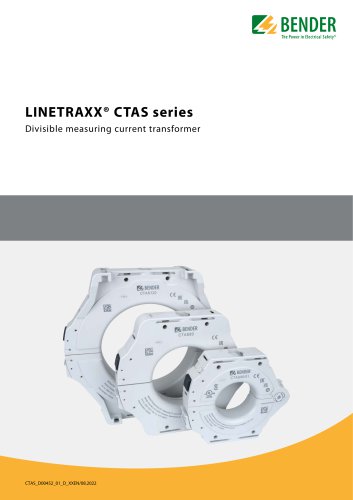 LINETRAXX® CTAS series
8 Pages
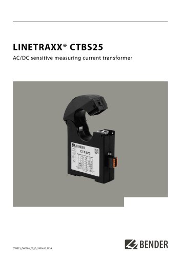 LINETRAXX® CTBS25
4 Pages
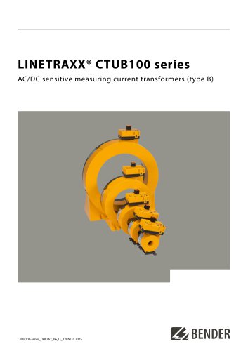 LINETRAXX® CTUB100 series
10 Pages
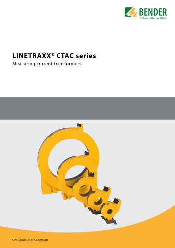 LINETRAXX® CTAC series
6 Pages
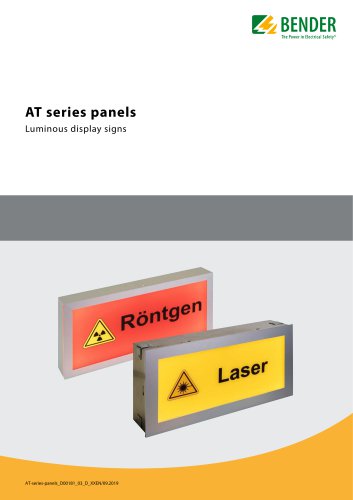 AT series
6 Pages
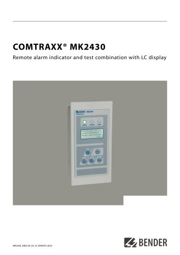 COMTRAXX® MK2430
6 Pages
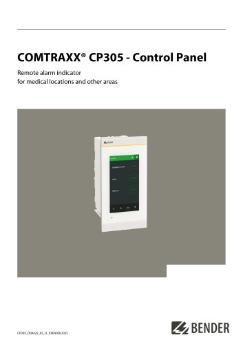 COMTRAXX® CP305
12 Pages
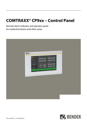 COMTRAXX® CP9xx
8 Pages
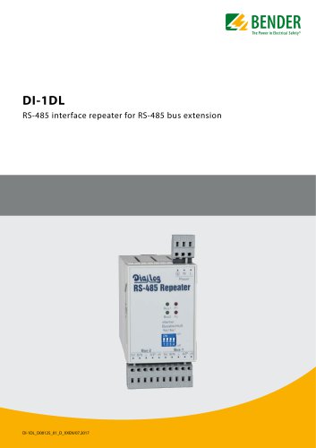 DI-1DL
4 Pages
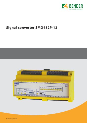 SMO482P-12
4 Pages
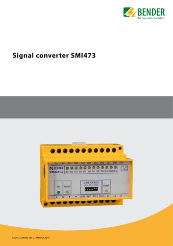 Signal converter SMI473
4 Pages
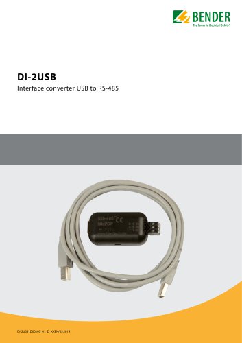 DI-2USB
4 Pages
 COMTRAXX® COM463BC
7 Pages
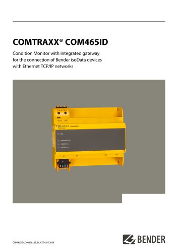 COMTRAXX® COM465ID
8 Pages
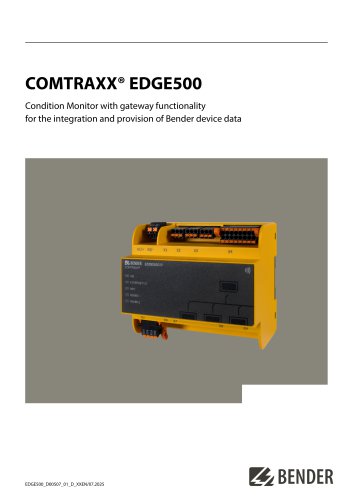 COMTRAXX® EDGE500
12 Pages
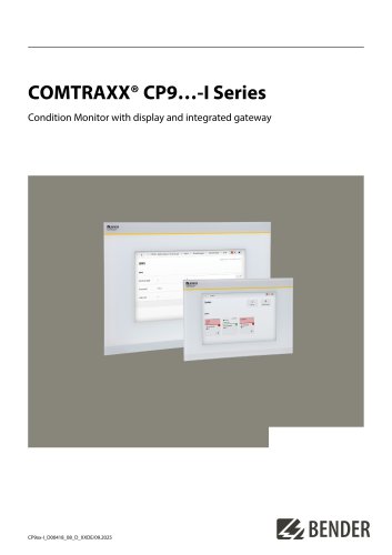 COMTRAXX® CP9…-I Series
10 Pages
 POWERSCOUT®
8 Pages
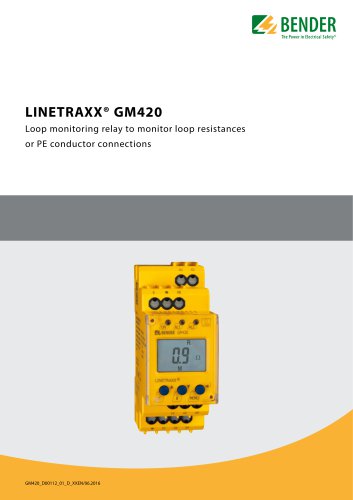 LINETRAXX® GM420
6 Pages
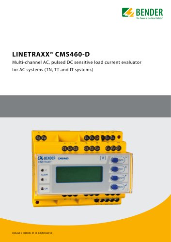 LINETRAXX® CMS460-D
10 Pages
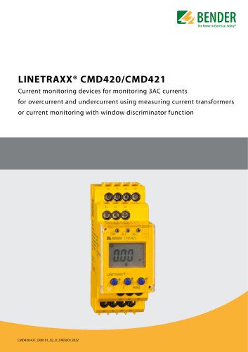 LINETRAXX® CMD420/CMD421
6 Pages
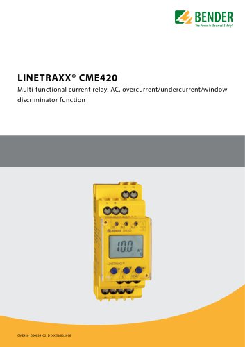 LINETRAXX® CME420
6 Pages
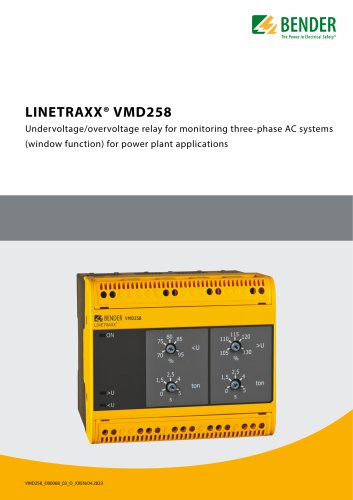 LINETRAXX® VMD258
6 Pages
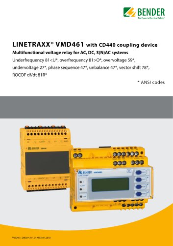 LINETRAXX® VMD461
10 Pages
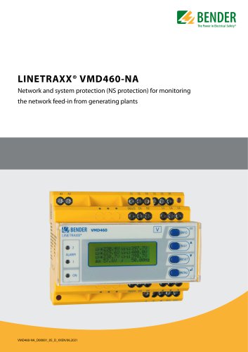 LINETRAXX® VMD460-NA
8 Pages
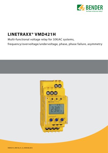 LINETRAXX® VMD421H
6 Pages
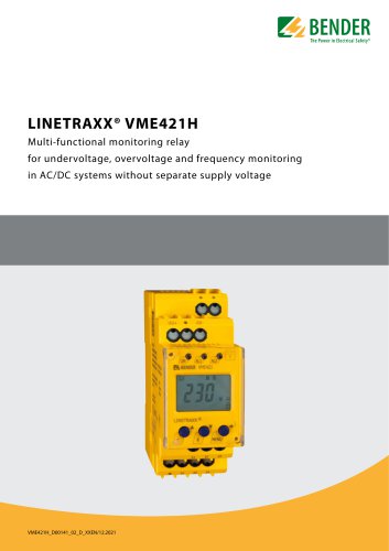 LINETRAXX® VME421H
6 Pages
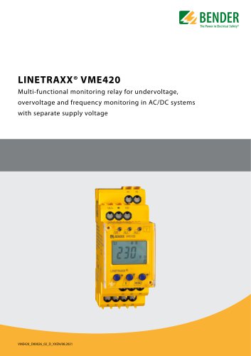 LINETRAXX® VME420
6 Pages
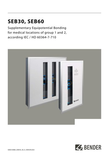 SEB30, SEB60
8 Pages
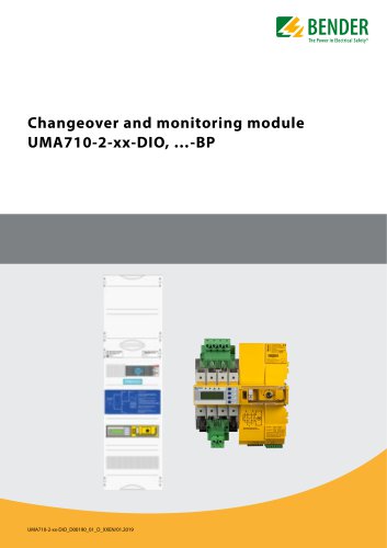 UMA710-2-xx-DIO, …-BP
6 Pages
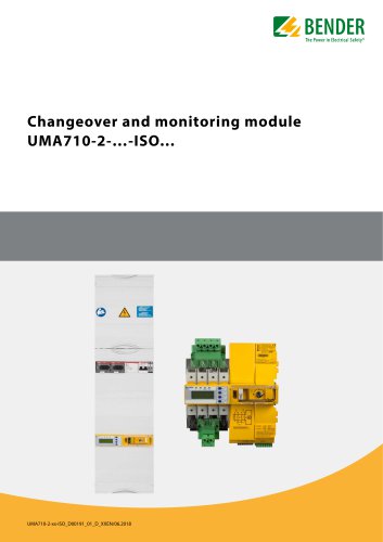 UMA710-2-…-ISO…
6 Pages
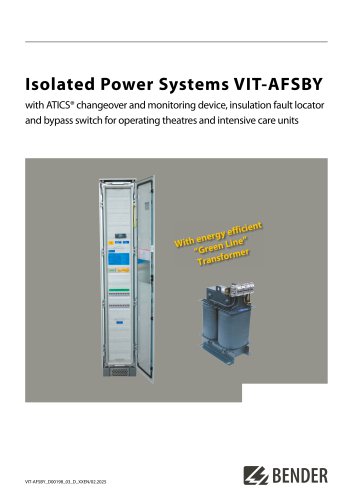 VIT-AFSBY
6 Pages
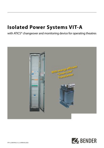 VIT-A
VIT-A6 Pages
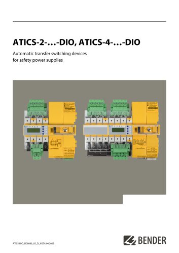 ATICS-2-…-DIO, ATICS-4-…-DIO
8 Pages
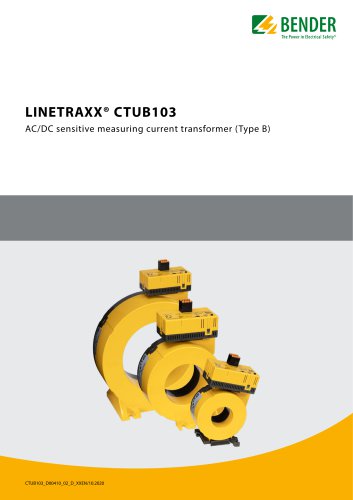 LINETRAXX® CTUB103
6 Pages
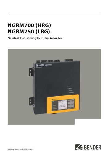 NGRM700 (HRG)/NGRM750 (LRG)
12 Pages
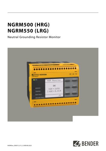 NGRM500 (HRG)/NGRM550 (LRG)
12 Pages
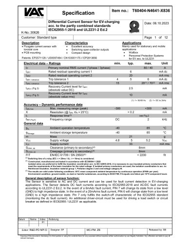 RDC125-5S
12 Pages
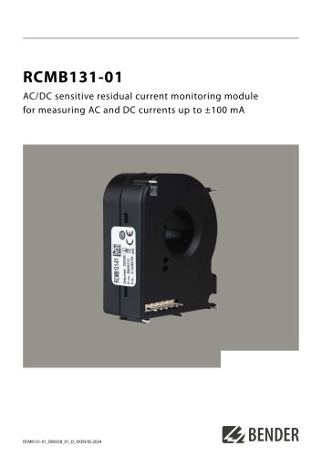 RCMB131-01
4 Pages
 RDC121
7 Pages
 RCMB123
7 Pages
 Residual current sensors
2 Pages
 LINETRAXX® RCM420
6 Pages
 LINETRAXX® RCMA420
6 Pages
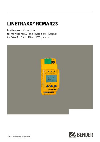 LINETRAXX® RCMA423
6 Pages
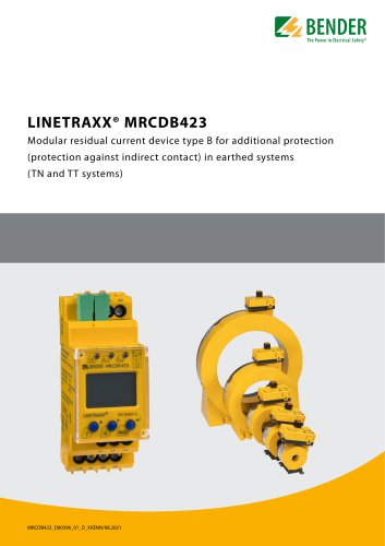 LINETRAXX® MRCDB423
6 Pages
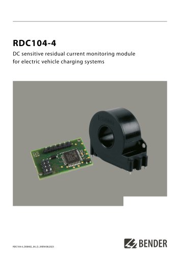 RDC104-4
6 Pages
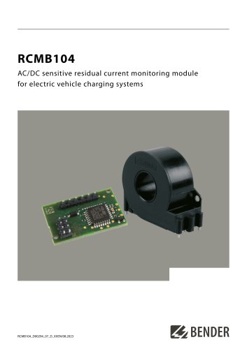 RCMB104
6 Pages
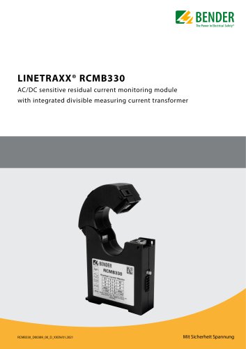 LINETRAXX® RCMB330
4 Pages
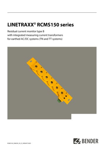 LINETRAXX® RCMS150 series
8 Pages
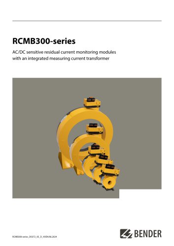 RCMB300-series
12 Pages
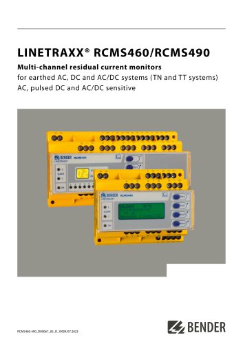 LINETRAXX® RCMS460/RCMS490
14 Pages
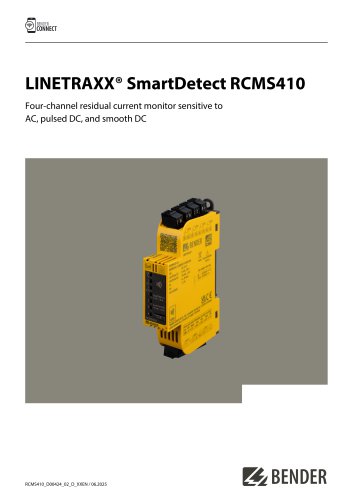 LINETRAXX® SmartDetect RCMS410
10 Pages
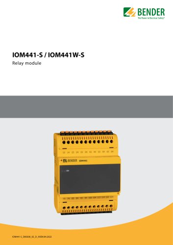 IOM441-S / IOM441W-S
4 Pages
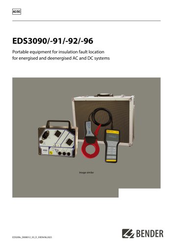 EDS3090/-91/-92/-96
14 Pages
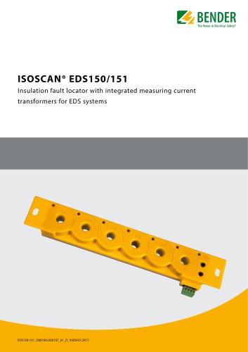 ISOSCAN® EDS150/151
6 Pages
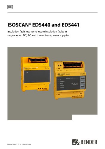 ISOSCAN® EDS440/EDS441
16 Pages
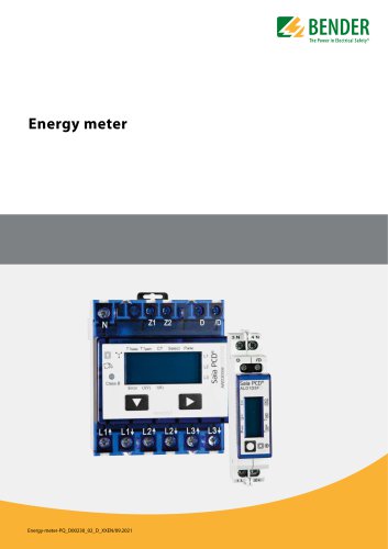 Energy meter
6 Pages
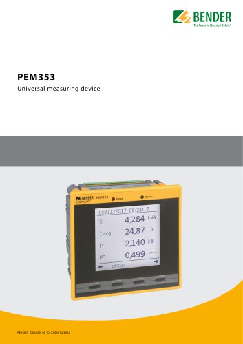 PEM353
8 Pages
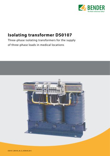 DS0107
6 Pages
 ESL0107
4 Pages
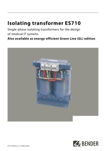 ES710
ES7108 Pages
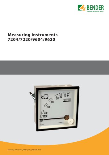 7204/7220/9604/9620
4 Pages
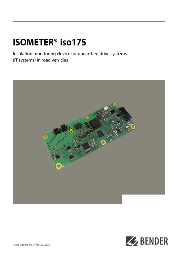 ISOMETER® iso175
8 Pages
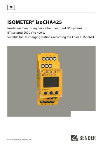 ISOMETER® isoCHA425
8 Pages
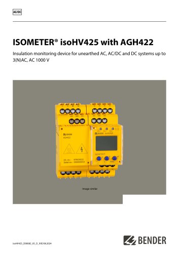 ISOMETER® isoHV425 with AGH422
10 Pages
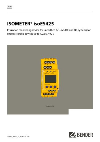 ISOMETER® isoES425
8 Pages
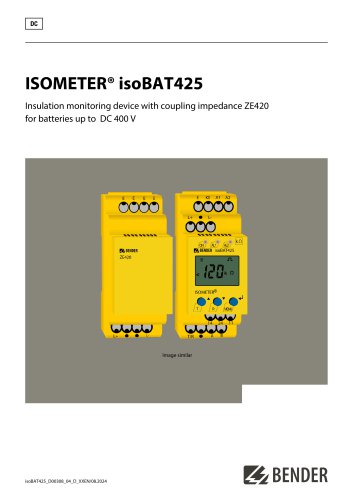 ISOMETER® isoBAT425
8 Pages
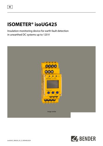 ISOMETER® isoUG425
6 Pages
 ISOMETER® isoRW425
8 Pages
 ISOMETER® isoGEN423
6 Pages
 ISOMETER® IR123P
4 Pages
 ISOMETER® IR423
6 Pages
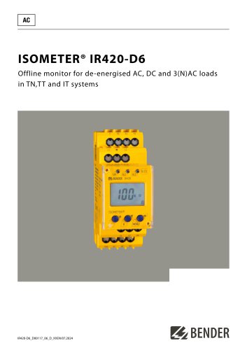 ISOMETER® IR420-D6
6 Pages
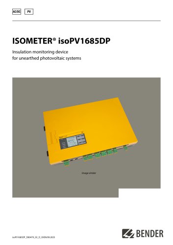 ISOMETER® isoPV1685DP
10 Pages
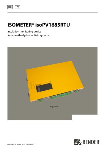 ISOMETER® isoPV1685RTU
8 Pages
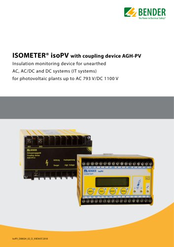 ISOMETER® isoPV
8 Pages
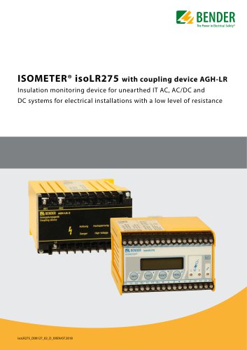 ISOMETER® isoLR275
6 Pages
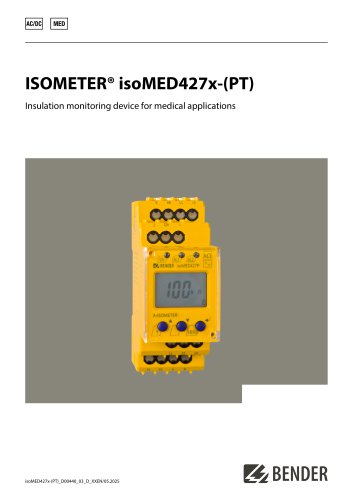 ISOMETER® isoMED427x-(PT)
6 Pages
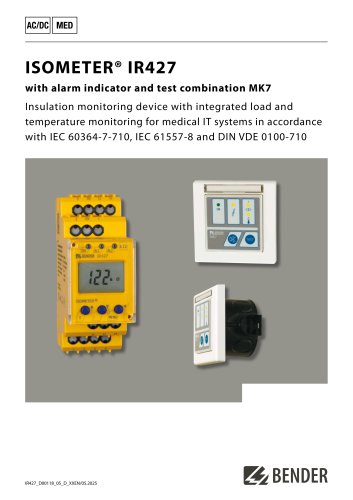 ISOMETER® IR427
8 Pages
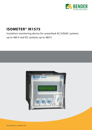 ISOMETER® IR1575
6 Pages
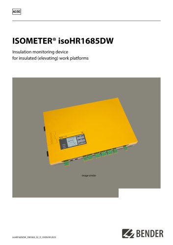 ISOMETER® isoHR1685DW
10 Pages
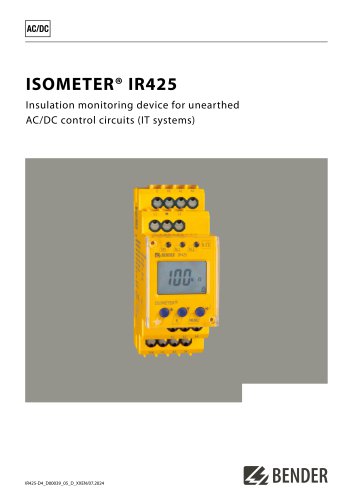 ISOMETER® IR425-D4
6 Pages
 ISOMETER® iso415R
2 Pages
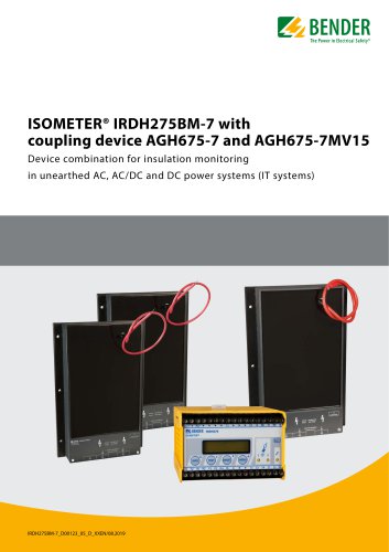 ISOMETER® IRDH275BM-7
6 Pages
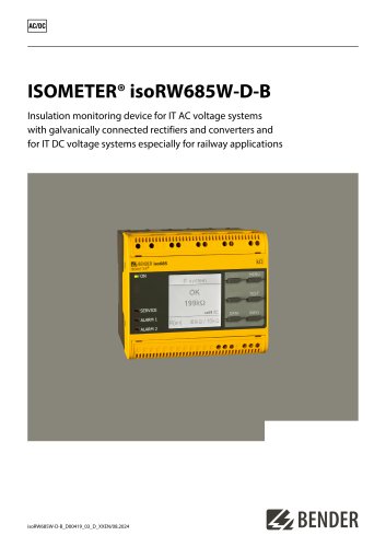 ISOMETER® isoRW685W-D-B
10 Pages
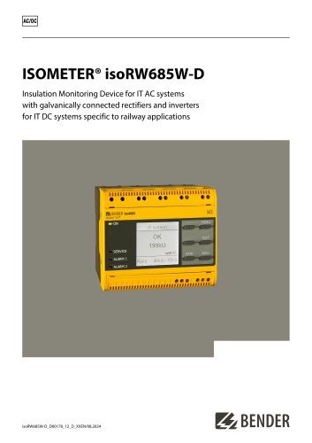 ISOMETER® isoRW685W-D
10 Pages
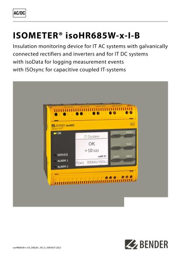 ISOMETER® isoHR685W-x-I-B
10 Pages
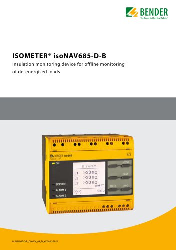 ISOMETER® isoNAV685-D-B
8 Pages
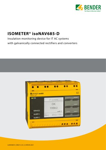 ISOMETER® isoNAV685-D
8 Pages
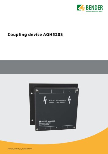 AGH520S
4 Pages
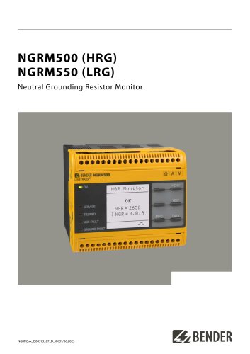 NGRM500 et NGRM550
12 Pages
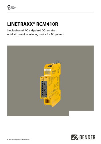 RCM410R
8 Pages
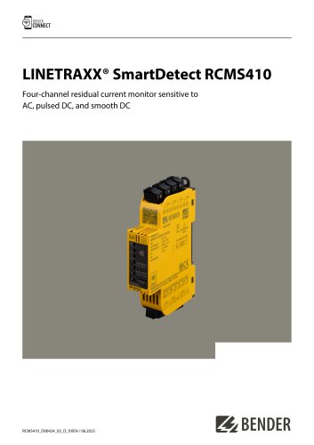 RCMS410
10 Pages
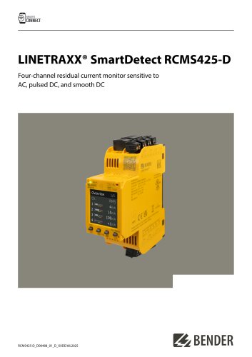 RCMS425-D
10 Pages
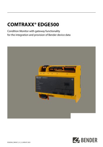 EDGE500
12 Pages
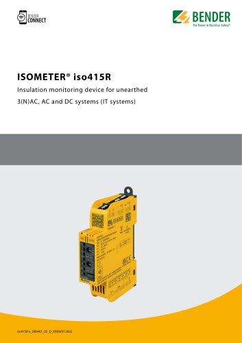 Iso415R
4 Pages
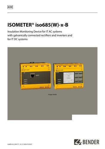 Iso685-x-B
12 Pages
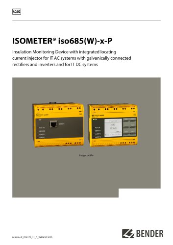 Iso685-x-P
14 Pages
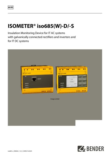 Iso685-x
12 Pages
 Data Centers
16 Pages
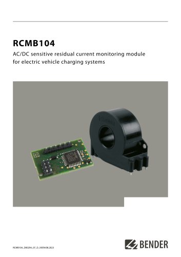 RCMB104
6 Pages
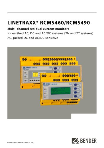 LINETRAXX® RCMS460 / RCMS490
14 Pages
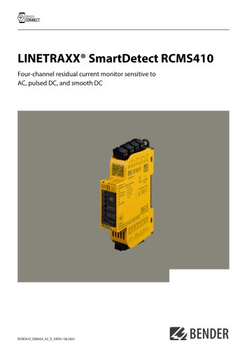 LINETRAXX® SmartDetect RCMS410
10 Pages
 Main Catalogue
486 Pages
- Power supply unit
- DC power supply
- AC/DC power supply
- BENDER transformer
- Measuring device
- BENDER dry transformer
- Junction block
- CE power supply
- Cloud-based software
- Single-output power supply
- Portable tester
- Power supply for industrial applications
- Monitoring software solution
- Communication gateway
- LED display panel
- BENDER IEC transformer
- BENDER current transformer
- Compact power supply
- Automatic tester