
- Catalogs
- BENDER GmbH & Co KG
- Iso685-x-B


- Company
- Products
- Catalogs
- News & Trends
- Exhibitions
Iso685-x-B
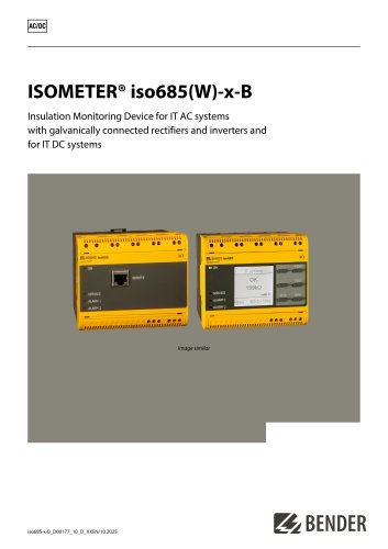
Iso685-x-B
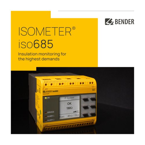
The ISOMETER® iso685(W)-x-B is designed to monitor insulation resistance in unearthed AC/DC main circuits (IT systems). It can extend the nominal voltage range via coupling devices and is unaffected by DC components in AC/DC systems. It also allows monitoring of de-energised systems with a separate supply voltage.
- Automatic adaptation to system leakage capacitance.
- Two adjustable response value ranges from 1 kΩ to 10 MΩ.
- Graphical LC display and connection monitoring.
- Automatic self-test and graphical representation of insulation resistance over time.
- History memory for storing alarm messages with date and time.
- Remote setting and diagnosis via Internet or Intranet.
- Communication via Modbus RTU, Modbus TCP, and web server.
The ISOMETER® iso685 complies with IEC 61557-8 and is applicable in various AC, 3(N)AC, AC/DC, and DC systems. It features different variants, including the iso685-D with an integrated display and the iso685-S sensor variant, which requires a front panel for operation.
The device continuously monitors insulation resistance and triggers an alarm if it falls below a preset value. It uses a microprocessor-controlled measuring circuit and stores settings in a fail-safe memory. The device can be configured for different system types and extended with coupling devices for a wider voltage range.
- Modbus TCP and RTU for communication.
- BCOM for Ethernet communication.
- RS-485 for sensor bus communication.
- Integrated web server for parameter settings.
- iso685(W)-D: Includes a graphical LC display.
- iso685(W)-S: Operated with FP200(W) and lacks a display.
Details on connection requirements, including power supply, system monitoring, and relay interfaces. Emphasizes the need for proper connection checks and functional tests before commissioning.
- Rated voltage: 1000 V, Overvoltage category III.
- Supply voltage range: AC/DC 24…240 V.
- Nominal system voltage range: AC 0…690 V, DC 0…1000 V.
- Response values: 1 kΩ to 10 MΩ with a relative uncertainty of ±15%.
- Measuring range: 0.1 kΩ to 20 MΩ.
- Alarms: Includes DC− alarm, DC+ alarm, symmetrical alarm, device error, common alarm, measurement complete, device inactive, and DC offset alarm. Note that DC alarms are applicable only for Un ≥ 50 V.
- Electrical Endurance: Rated for 10,000 operating cycles under specified conditions.
- Contact Data: Complies with IEC 60947-5-1, with various utilization categories and rated operational voltages and currents.
- Environmental Conditions: Operating temperature ranges from −25 to +55 °C, with transport and storage conditions specified. EMC compliance is according to IEC 61326-2-4.
- Screw-type Terminals: Nominal current ≤ 10 A, with specific conductor sizes and stripping lengths.
- Push-wire Terminals: Nominal current ≤ 8 A, with detailed wire cross-section specifications.
- Complies with IEC 60721 for climatic and mechanical conditions, with specific classifications for stationary use, transport, and long-term storage.
- Mounting options include DIN rail and screw mounting, with specific requirements for best ventilation and temperature management.
- Developed in compliance with standards such as DIN EN 61557-8 and IEC 61557-8.
- Various models and options are available, including increased shock and vibration resistance versions.
- Accessories include mechanical components and connector kits.
- Dimensions and weight are specified, along with material and flammability class.
- Contact information for Bender GmbH & Co. KG is provided for further inquiries.
Catalog excerpts
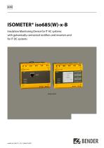
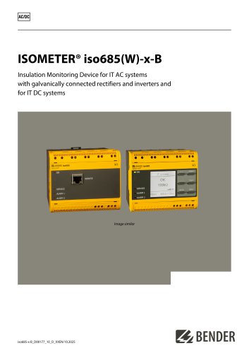
ISOMETER® iso685(W)-x-B Insulation Monitoring Device for IT AC systems with galvanically connected rectifiers and inverters and for IT DC systems Image similar
Open the catalog to page 1
The ISOMETER® monitors the insulation resistance of unearthed AC/DC main circuits (IT systems). For the iso685-x and iso685-x-B types, the operating range of the nominal voltage Un can be extended via coupling devices. DC components existing in AC/DC systems do not influence the operating characteristics. A separate supply voltage allows de-energised systems to be monitored too. The maximum permissible system leakage capacitance is provided in the technical data. Kr BENDER Insulation Monitoring Device for IT AC systems with galvanically connected rectifiers and inverters and Device features •...
Open the catalog to page 2
Function description The insulation monitoring device continuously monitors the entire insulation resistance of an IT system during operation and triggers an alarm when the value falls below a preset response value. For measurement, the device has to be connected between the IT system and the protective earth conductor (PE). A measuring current in the µA range is superimposed onto the system which is recorded and evaluated by a microprocessorcontrolled measuring circuit. The measuring time is dependent on the selected measurement profiles, the system leakage capacitance, the insulation resistance...
Open the catalog to page 3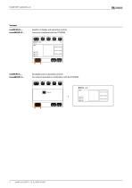
Graphic LC display and operating controls. Cannot be combined with the FP200(W). No display and no operating controls. Can only be operated in combination with the FP200(W).
Open the catalog to page 4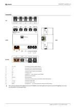
A ji3l A riTTTTTI 111ITTTT11111 rnTTI 111 miTI 111ITTTT1 Connection to the power supply voltage Us Connector for the IT system to be monitored Connector for the IT system to be monitored Connector for the IT system to be monitored Connection to PE Multifunctional I/O interface Ethernet interface Switchable terminating resistor for termination of the RS-485 interface Connector for alarm relay 1 Connector for alarm relay 2 isoxx685(W)-x-P... only: optional expansion interface for Bender products J The connection between the iso685 device and an FP200(W) can be interrupted and restored at any time...
Open the catalog to page 5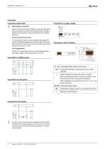
Connection requirements Connection to a supply voltage J Check proper connection! Prior to commissioning the installation, check that the device has been properly connected and check the device functions. Perform a functional test using an earth fault via a suitable resistance. Prevent measurement errors! If a monitored AC system contains galvanically coupled DC circuits, the following applies: An insulation fault can only be detected with its correct value when the rectifier valves carry a minimum current of > 10 mA. Use 60/75 °C copper lines only! For UL and CSA applications, the supply voltage...
Open the catalog to page 6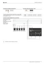
Connection with standard patch cable (RJ45/no crossover cable) to other ISOMETER®s or interconnection of several ISOMETER®s in star topology via a switch. Connection using the AGH204S-4 (Art. No.: B914013) Nominal voltage with rectifier: Nominal voltage without rectifier: AC 0...1650 V Relative uncertainty: For further connection examples, see manual.
Open the catalog to page 7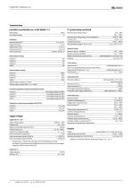
Technical data Measuring circuit (IC1) Supply circuit (IC2) Output circuit 1 (IC3) Output circuit 2 (IC4) Control circuit (IC5) IT system being monitored Nominal system voltage range Un AC 0.690 V Nominal system voltage range Un for UL applications AC/DC 0.600 V Max. alternating voltage U~ (for f < 4 Hz) Umax = 50 V x (1 + f,2) Rated impulse voltage Response values Response value Rani (ALARM 1) 1 kO . 10 MO Response value Ran2 (ALARM 2) 1 kO . 10 MO Relative uncertainty (acc. to IEC 61557-8) profile-dependent, ±15 %, min. ±1 kO Rated insulation voltage Pollution degree outside (Un < 690 V) 3...
Open the catalog to page 8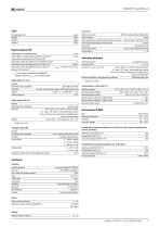
SERVICE yellow Interface / protocol Data rate Mode 1 Cable: twisted pairs, shield connected to PE on one side recommended: J-Y(St)Y min. 2x0.8 Cable length (depending on the baud rate) Cable length X1 (unshielded cable) < 10 m Cable length X1 (shielded cable, shield connected to PE < 100 m on one side) recommended: J-Y(St)Y min. 2x0.8 Max output current for supply via X1+/X1GND per output 1 A Max output current for supply via A1/A2 in total on X1 200 mA Max output current for supply via A1/A2 in total on X1 I_maxxi = 10 mA + 7 mA / V x Us’ * Us is the supply voltage of the ISOMETER®. Negative...
Open the catalog to page 9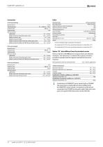
continuous operation display-oriented * IP40 IP20 IEC 60715 3 x M4 with mounting clip polycarbonate V-0 Screw-type terminals Nominal current Tightening torque Conductor sizes Wire cross-section flexible with ferrule with/without plastic sleeve 0.25___2.5 mm2 Multiple conductor, rigid 0.2___1 mm2 Multiple conductor, flexible 0.2 1.5 mm2 Multiple conductor, flexible with ferrule without plastic sleeve 0.25___1 mm2 Multiple conductor, flexible with TWIN ferrule with plastic sleeve 0.5___1.5 mm2 Push-wire terminals Wire cross-section flexible with ferrule with/without plastic sleeve 0.25 2.5 mm2...
Open the catalog to page 10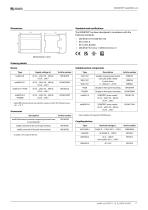
The ISOMETER® has been developed in compliance with the following standards: Ordering details Suitable system components Option W: Increased shock and vibration resistance 3K23; 3M12; Bezeichnung -40.. .+70 °C included in the scope of delivery Only available with separate FP200(W) panel Coupling devices
Open the catalog to page 11
Bender GmbH & Co. KG Londorfer Straße 65 35305 Grünberg Germany Tel.: +49 6401 807-0 [email protected] www.bender.de © Bender GmbH & Co. KG, Germany Subject to change! The specified standards take into account the edition valid until 10.2025 unless otherwise indicated.
Open the catalog to page 12All BENDER GmbH & Co KG catalogs and technical brochures
 CD25000
4 Pages
 CD14400
4 Pages
 CD1000
4 Pages
 AUR381Z
4 Pages
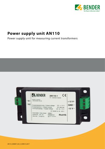 AN110
AN1104 Pages
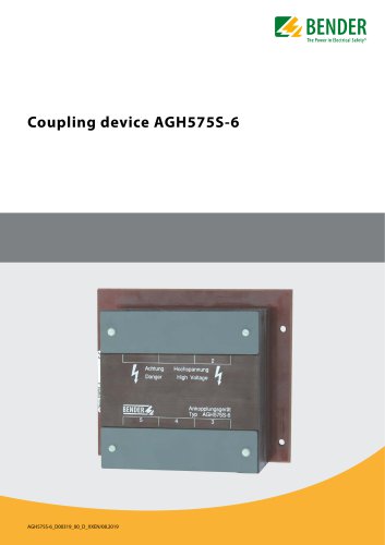 AGH575S-6
4 Pages
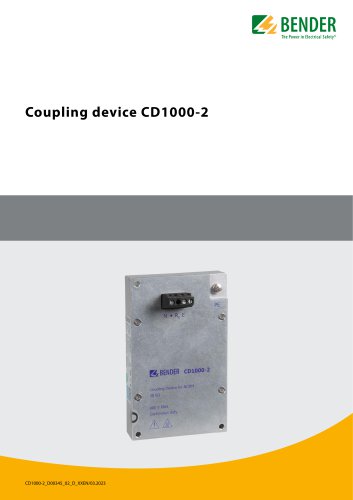 CD1000-2
4 Pages
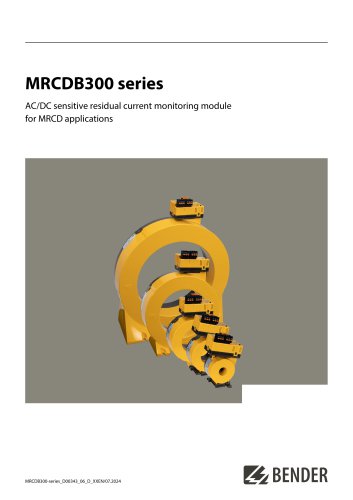 MRCDB300 series
12 Pages
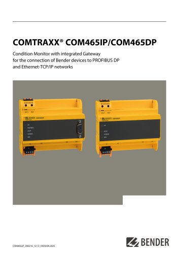 COMTRAXX® COM465IP/COM465DP
10 Pages
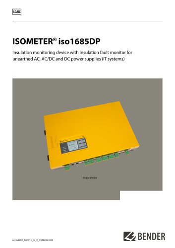 ISOMETER® iso1685DP
10 Pages
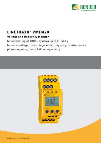 LINETRAXX® VMD420
6 Pages
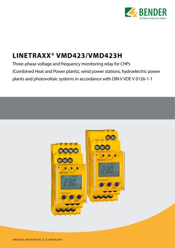 LINETRAXX® VMD423/VMD423H
6 Pages
 ISOMETER® iso685(W)-x-B
12 Pages
 ISOMETER® iso685
12 Pages
 UNIMET® 810ST
4 Pages
 UNIMET® 610ST
4 Pages
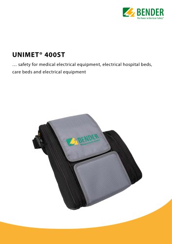 UNIMET® 400ST
4 Pages
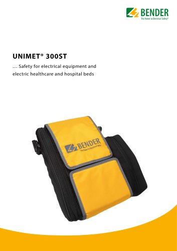 UNIMET® 300ST
4 Pages
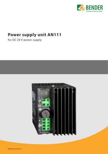 AN111
AN1114 Pages
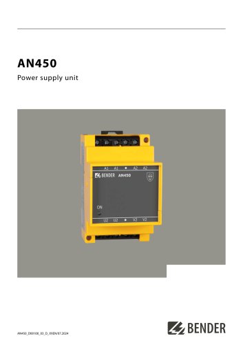 AN450
AN4504 Pages
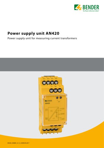 AN420
AN4204 Pages
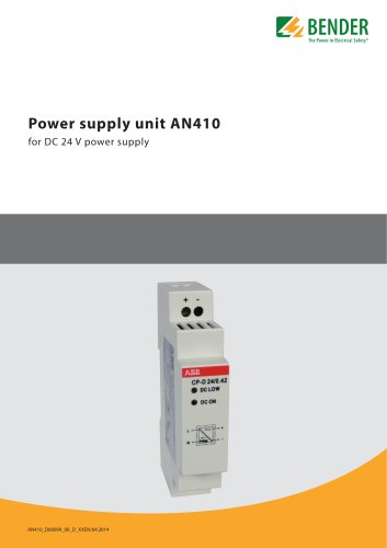 AN410
AN4104 Pages
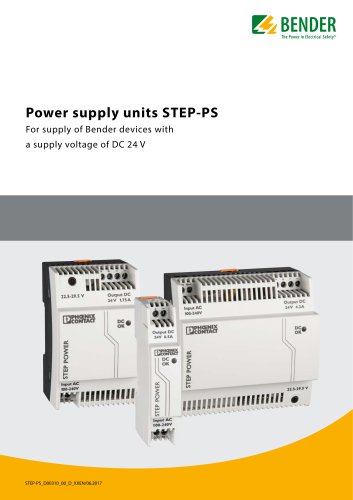 STEP-PS
8 Pages
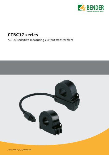 CTBC17 series
8 Pages
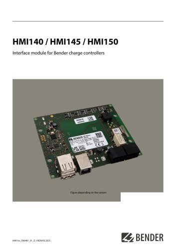 HMI140 / HMI145 / HMI150
6 Pages
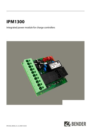 IPM1300
8 Pages
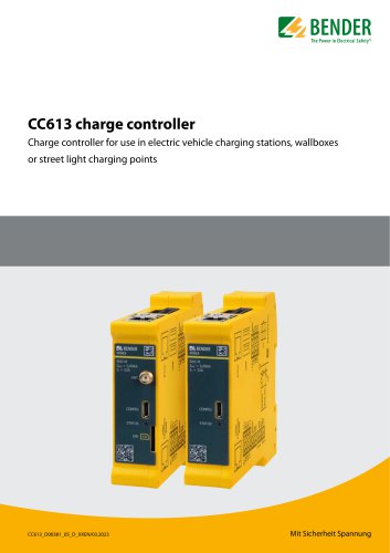 CC613
CC6136 Pages
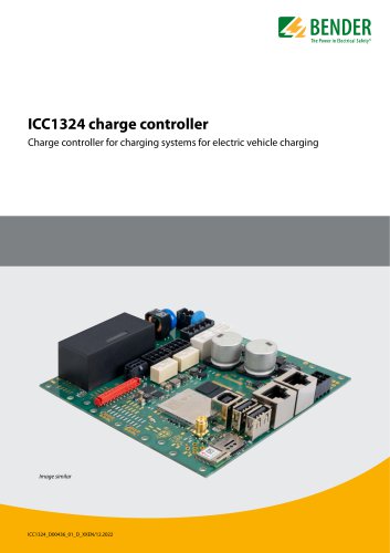 ICC1324
8 Pages
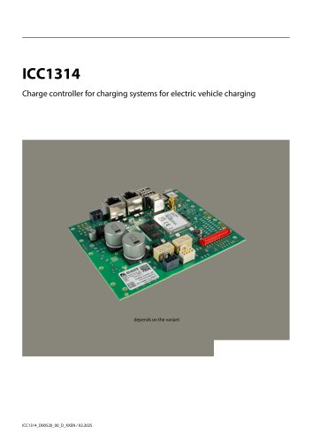 ICC1314
8 Pages
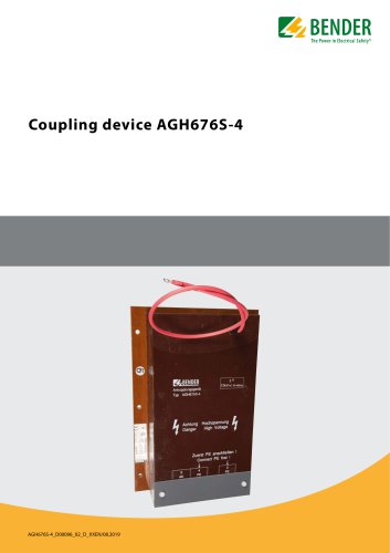 AGH676S-4
4 Pages
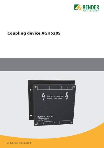 AGH520S
4 Pages
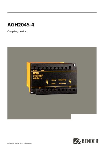 AGH204S-4
4 Pages
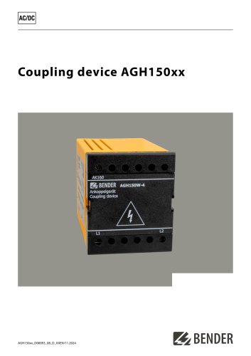 AGH150xx
4 Pages
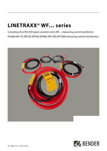 LINETRAXX® WF… series
4 Pages
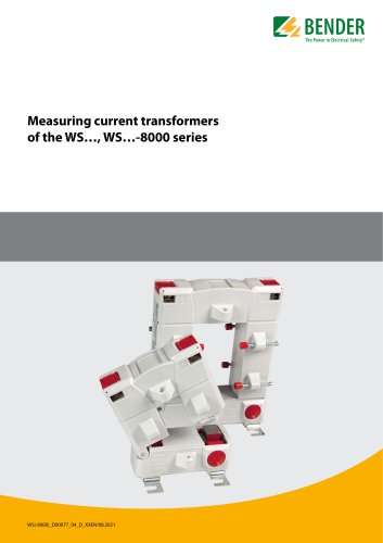 WS…, WS…-8000 series
4 Pages
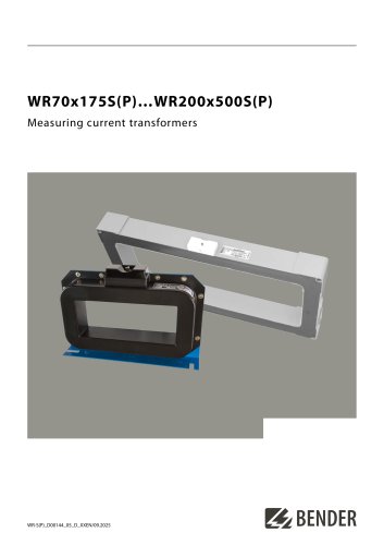 WR70x175S(P)…WR200x500S(P)
4 Pages
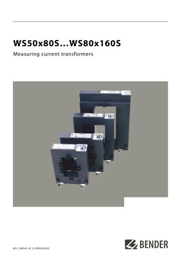 WS50x80S…WS80x160S
4 Pages
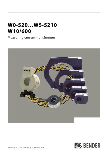 W0-S20…W5-S210 W10/600
4 Pages
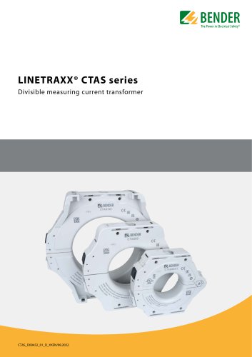 LINETRAXX® CTAS series
8 Pages
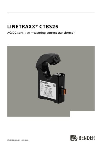 LINETRAXX® CTBS25
4 Pages
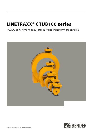 LINETRAXX® CTUB100 series
10 Pages
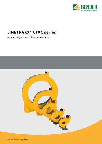 LINETRAXX® CTAC series
6 Pages
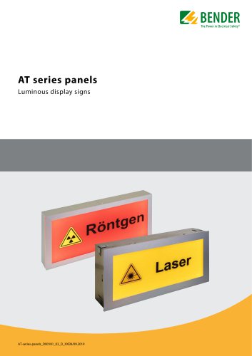 AT series
6 Pages
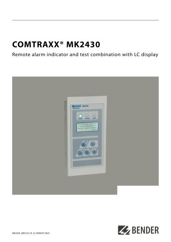 COMTRAXX® MK2430
6 Pages
 COMTRAXX® CP305
12 Pages
 COMTRAXX® CP9xx
8 Pages
 DI-1DL
4 Pages
 SMO482P-12
4 Pages
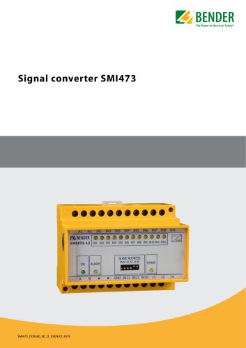 Signal converter SMI473
4 Pages
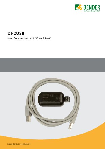 DI-2USB
4 Pages
 COMTRAXX® COM463BC
7 Pages
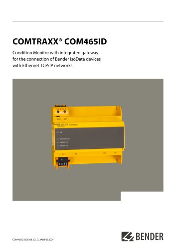 COMTRAXX® COM465ID
8 Pages
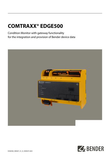 COMTRAXX® EDGE500
12 Pages
 COMTRAXX® CP9…-I Series
10 Pages
 POWERSCOUT®
8 Pages
 LINETRAXX® GM420
6 Pages
 LINETRAXX® CMS460-D
10 Pages
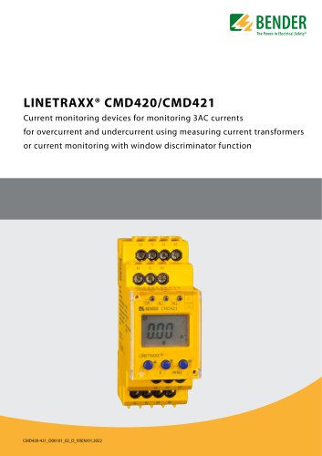 LINETRAXX® CMD420/CMD421
6 Pages
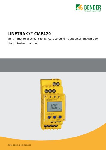 LINETRAXX® CME420
6 Pages
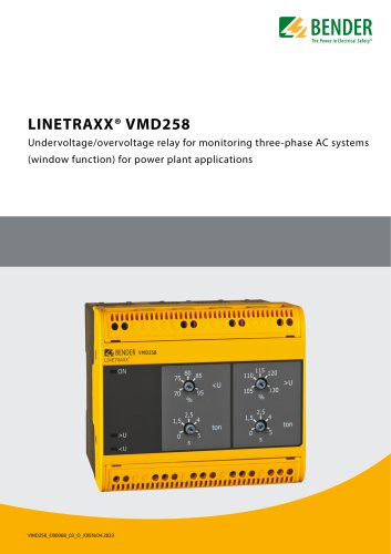 LINETRAXX® VMD258
6 Pages
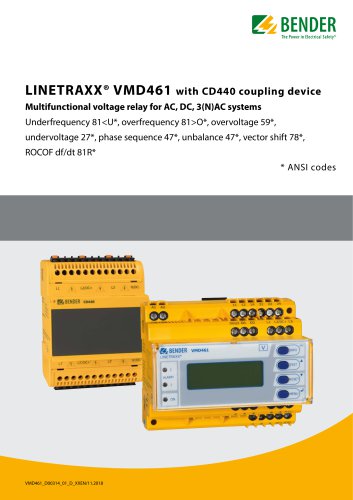 LINETRAXX® VMD461
10 Pages
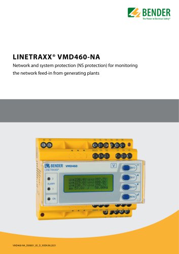 LINETRAXX® VMD460-NA
8 Pages
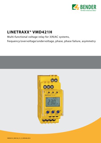 LINETRAXX® VMD421H
6 Pages
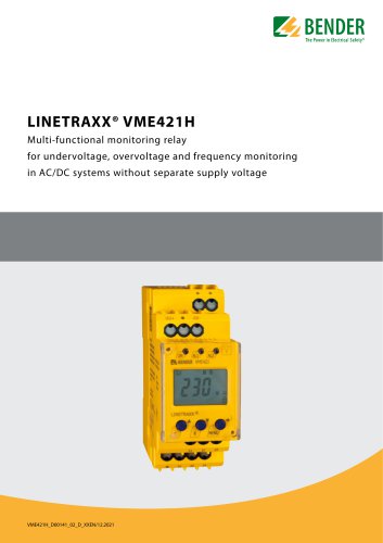 LINETRAXX® VME421H
6 Pages
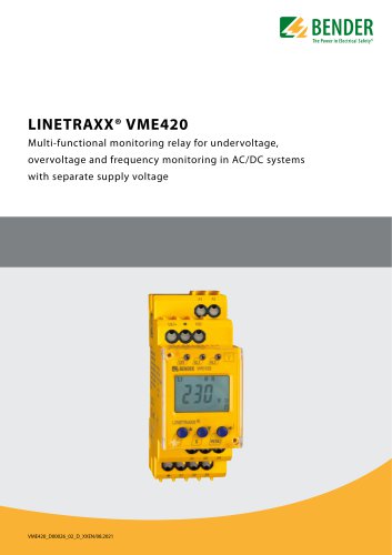 LINETRAXX® VME420
6 Pages
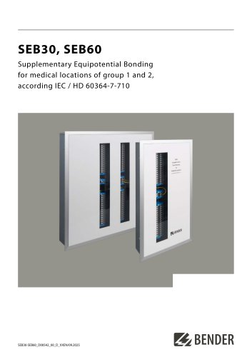 SEB30, SEB60
8 Pages
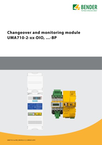 UMA710-2-xx-DIO, …-BP
6 Pages
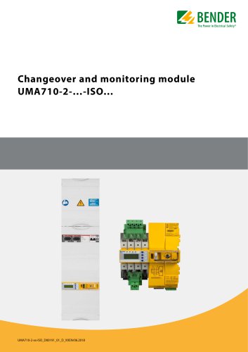 UMA710-2-…-ISO…
6 Pages
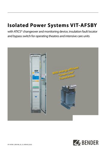 VIT-AFSBY
6 Pages
 VIT-A
VIT-A6 Pages
 ATICS-2-…-DIO, ATICS-4-…-DIO
8 Pages
 LINETRAXX® CTUB103
6 Pages
 NGRM700 (HRG)/NGRM750 (LRG)
12 Pages
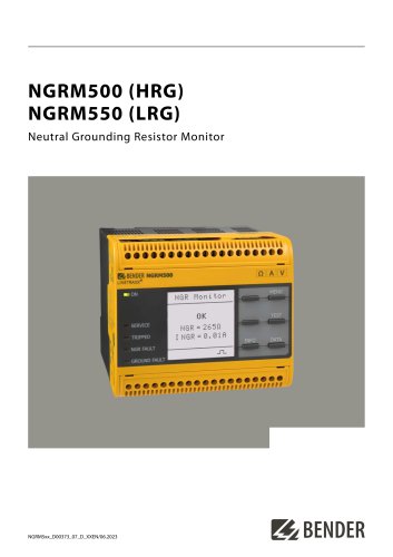 NGRM500 (HRG)/NGRM550 (LRG)
12 Pages
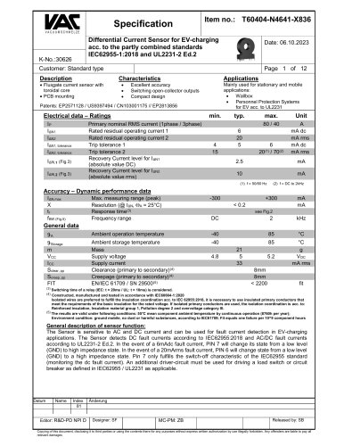 RDC125-5S
12 Pages
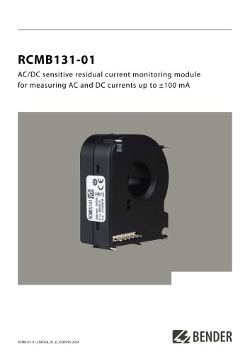 RCMB131-01
4 Pages
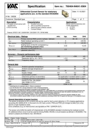 RDC121
7 Pages
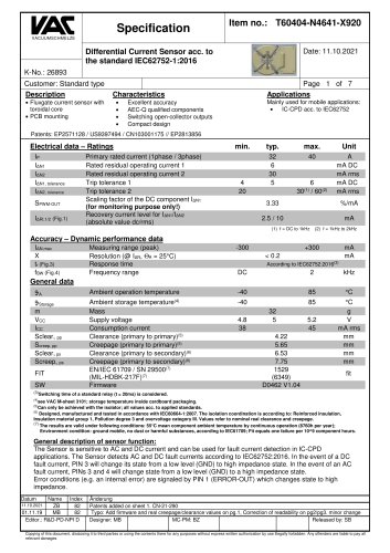 RCMB123
7 Pages
 Residual current sensors
2 Pages
 LINETRAXX® RCM420
6 Pages
 LINETRAXX® RCMA420
6 Pages
 LINETRAXX® RCMA423
6 Pages
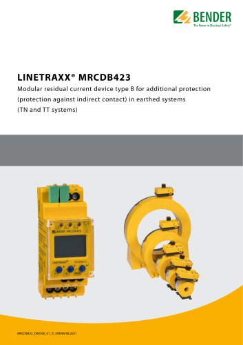 LINETRAXX® MRCDB423
6 Pages
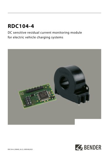 RDC104-4
6 Pages
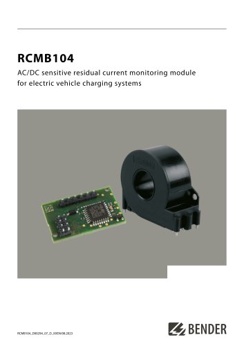 RCMB104
6 Pages
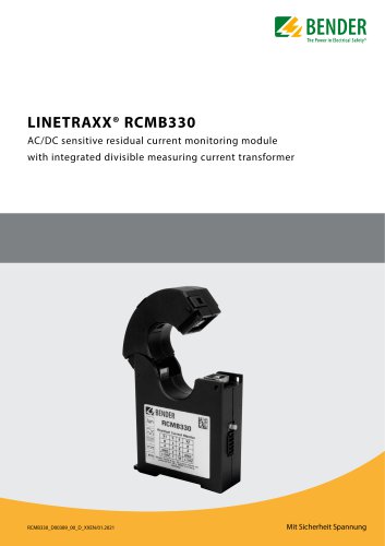 LINETRAXX® RCMB330
4 Pages
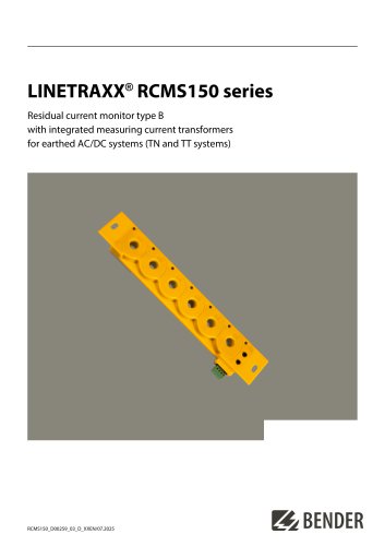 LINETRAXX® RCMS150 series
8 Pages
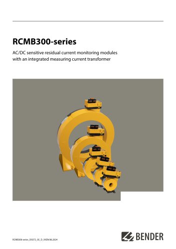 RCMB300-series
12 Pages
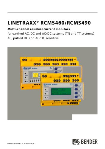
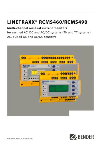 LINETRAXX® RCMS460/RCMS490
14 Pages
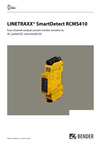
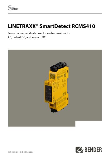 LINETRAXX® SmartDetect RCMS410
10 Pages
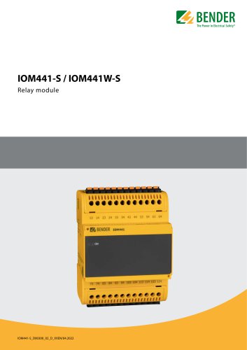 IOM441-S / IOM441W-S
4 Pages
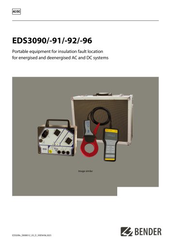 EDS3090/-91/-92/-96
14 Pages
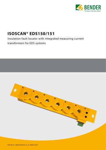 ISOSCAN® EDS150/151
6 Pages
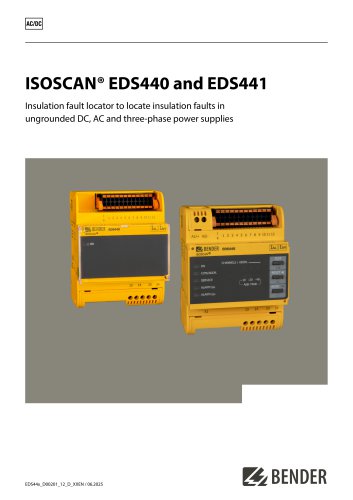 ISOSCAN® EDS440/EDS441
16 Pages
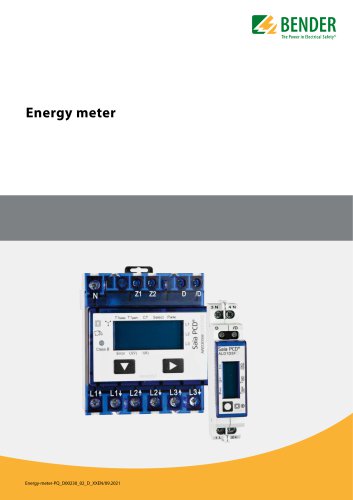 Energy meter
6 Pages
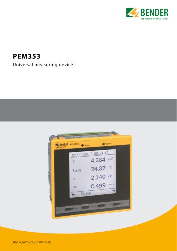 PEM353
8 Pages
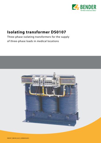 DS0107
6 Pages
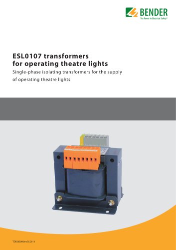 ESL0107
4 Pages
 ES710
ES7108 Pages
 7204/7220/9604/9620
4 Pages
 ISOMETER® iso175
8 Pages
 ISOMETER® isoCHA425
8 Pages
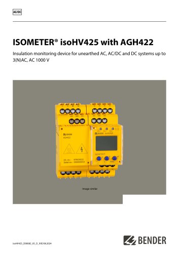 ISOMETER® isoHV425 with AGH422
10 Pages
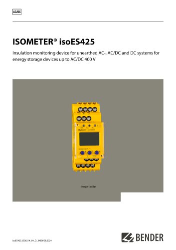 ISOMETER® isoES425
8 Pages
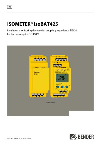 ISOMETER® isoBAT425
8 Pages
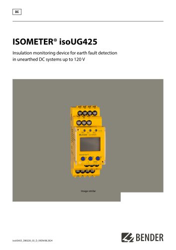 ISOMETER® isoUG425
6 Pages
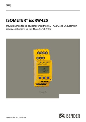 ISOMETER® isoRW425
8 Pages
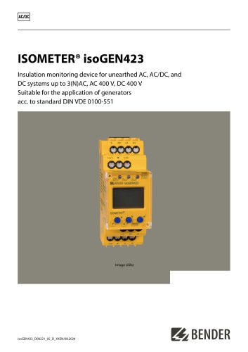 ISOMETER® isoGEN423
6 Pages
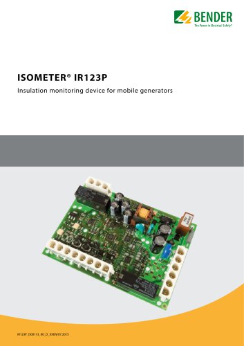 ISOMETER® IR123P
4 Pages
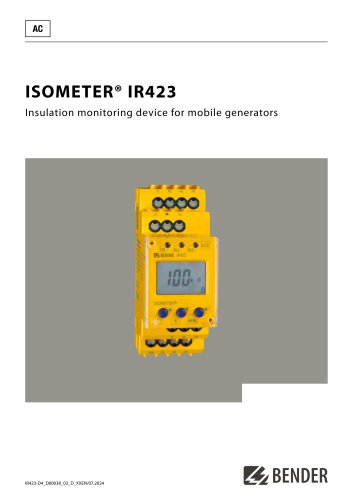 ISOMETER® IR423
6 Pages
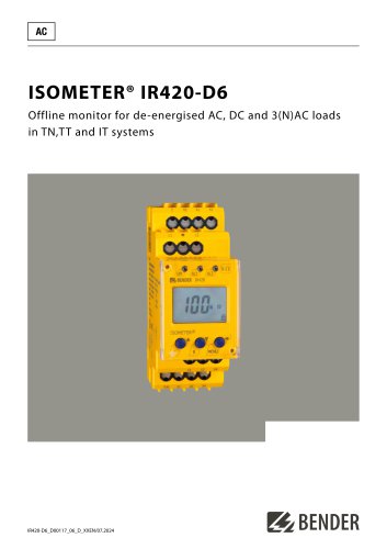 ISOMETER® IR420-D6
6 Pages
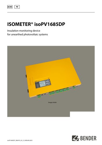 ISOMETER® isoPV1685DP
10 Pages
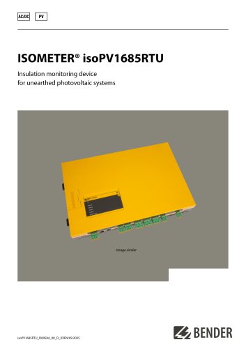 ISOMETER® isoPV1685RTU
8 Pages
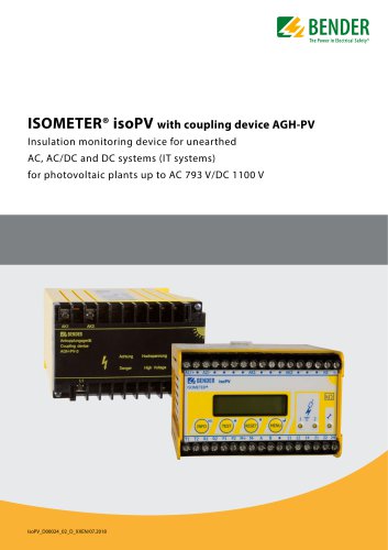 ISOMETER® isoPV
8 Pages
 ISOMETER® isoLR275
6 Pages
 ISOMETER® isoMED427x-(PT)
6 Pages
 ISOMETER® IR427
8 Pages
 ISOMETER® IR1575
6 Pages
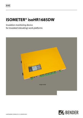 ISOMETER® isoHR1685DW
10 Pages
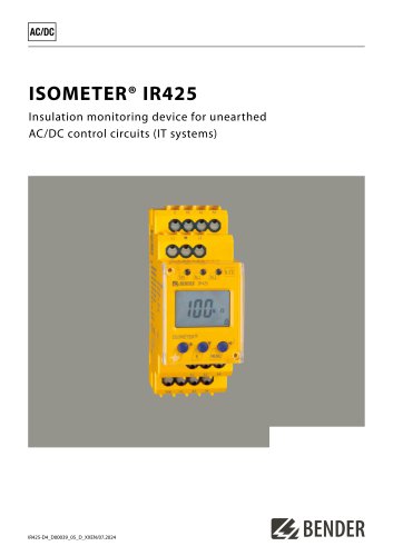 ISOMETER® IR425-D4
6 Pages
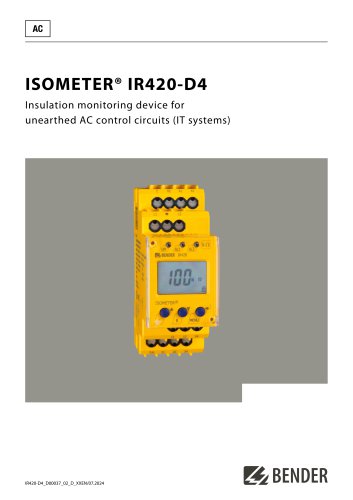 ISOMETER® IR420-D4
6 Pages
 ISOMETER® iso415R
2 Pages
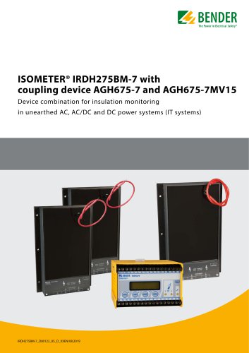 ISOMETER® IRDH275BM-7
6 Pages
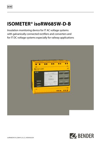 ISOMETER® isoRW685W-D-B
10 Pages
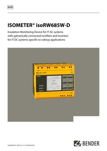 ISOMETER® isoRW685W-D
10 Pages
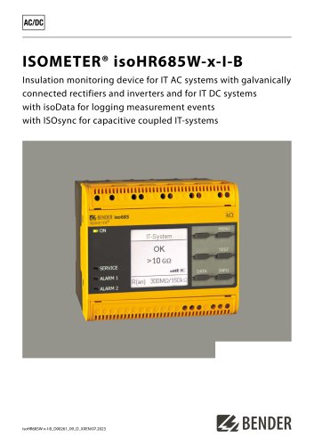 ISOMETER® isoHR685W-x-I-B
10 Pages
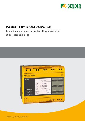 ISOMETER® isoNAV685-D-B
8 Pages
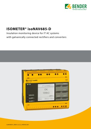 ISOMETER® isoNAV685-D
8 Pages
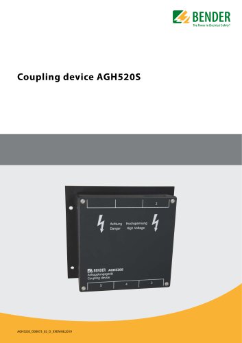 AGH520S
4 Pages
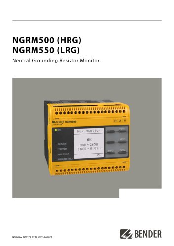 NGRM500 et NGRM550
12 Pages
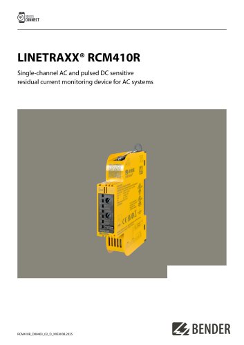 RCM410R
8 Pages
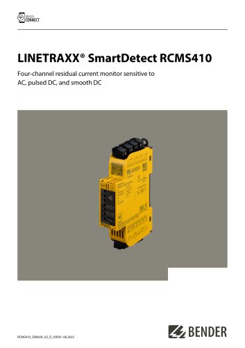 RCMS410
10 Pages
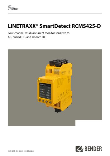 RCMS425-D
10 Pages
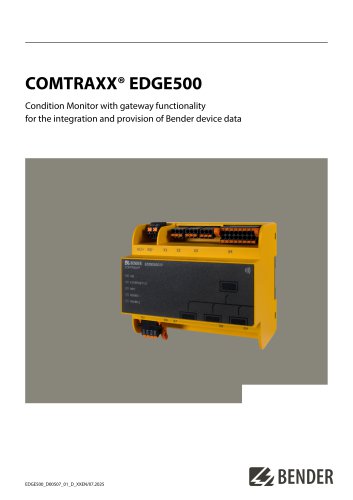 EDGE500
12 Pages
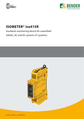 Iso415R
4 Pages
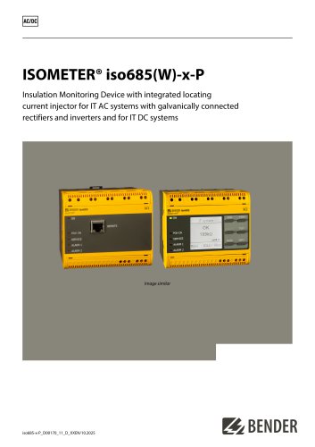 Iso685-x-P
14 Pages
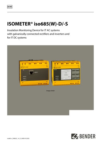 Iso685-x
12 Pages
 Data Centers
16 Pages
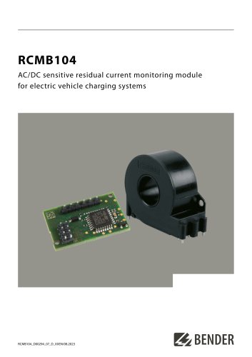 RCMB104
6 Pages
 LINETRAXX® RCMS460 / RCMS490
14 Pages
 LINETRAXX® SmartDetect RCMS410
10 Pages
 Main Catalogue
486 Pages
- DC power supply
- AC/DC power supply
- BENDER transformer
- Measuring device
- BENDER dry transformer
- Junction block
- CE power supply
- Cloud-based software
- Single-output power supply
- Portable tester
- Power supply for industrial applications
- Monitoring software solution
- LED display panel
- Communication gateway
- BENDER IEC transformer
- BENDER current transformer
- Compact power supply
- Automatic tester