- Catalogs
- BENDER GmbH & Co KG
- COMTRAXX® EDGE500
- Company
- Products
- Catalogs
- News & Trends
- Exhibitions
COMTRAXX® EDGE500
1 /12Pages
COMTRAXX® EDGE500
1 /12Pages
Catalog excerpts
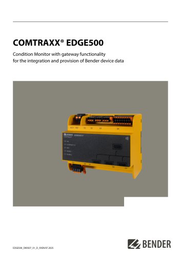
COMTRAXX® EDGE500 Condition Monitor with gateway functionality for the integration and provision of Bender device data
Open the catalog to page 1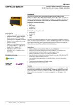
COMTRAXX® EDGE500 Condition Monitor with gateway functionality for the integration and provision of Bender device data Device features • Condition monitor for Bender systems • Integrated modular gateway between Bender systems and TCP/IP enables remote access via LAN, WAN or Internet • Range of functions adjustable through function modules • Support of devices that are connected to the internal BMS bus, via BCOM, via Modbus RTU or Modbus TCP • Individual visualisation can be generated, which is displayed via the web browser Data transfer interfaces Intended use The EDGE500 converts alarms, measured...
Open the catalog to page 2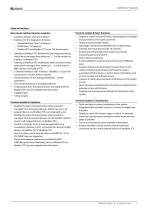
Basic device (without function modules) • Condition monitor with web interface • Interfaces for the integration of devices - Modbus RTU and Modbus TCP (max. 247 devices each) • Gateway to Modbus TCP: Reading the latest measured values, status/alarm messages from addresses 1...5 of the respective interface via Modbus TCP • Gateway to Modbus RTU: Reading the latest measured values, status/alarm messages from addresses 1.5 of the internal BMS interface via Modbus RTU • 3 Ethernet interfaces with 10 Mbit/s | 100 Mbit/s | 1 Gbit/s for remote access via LAN, WAN or Internet • Parameterisation of the...
Open the catalog to page 3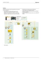
Interfaces EDGE500 communicates with the assigned devices and systems via various interfaces: • Internal BMS bus (RS-485) for Bender systems such as ISOSCAN® EDS150, LINETRAXX® RCMS460-D or ATICS®. EDGE500 can be operated as a master or as a slave. When operated as a master, requests are answered more quickly. Block diagram • BCOM (Ethernet) for Bender systems with Ethernet communication such as ISOMETER® iso685-D • Modbus RTU (RS-485) for Bender devices such as LINETRAXX® SmartDetect RCMS410 • Modbus TCP (Ethernet) for Bender devices such as LINETR
Open the catalog to page 4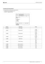
Connections and control elements For UL applications, the following must be observed: • Maximum ambient temperature: 55 °C • Use 60/75°C copper lines only
Open the catalog to page 5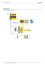
Connection diagram Connection diagram EDGE500 (Example)
Open the catalog to page 6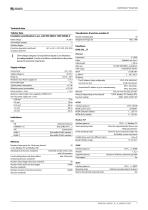
Technical data Cable length Data rate HTTP mode DHCP to,, (DHCP) Supported devices Trap support Tabular data Insulation coordination in acc. with IEC 60664-1/IEC 60664-3 insulation) between Overvoltage category II and pollution degree 2 are related to the relay contacts. Further insulation coordination takes place based on functional separation. Supply voltage Protection class Power supply unit 2 or 3 Typical power consumption < 3.5 W Maximum power consumption < 10.5 W Maximum cable length when supplied via B95061210 (24 V DC power supply unit 1.75 A) Operation indicator Data traffic ETH1...2...
Open the catalog to page 7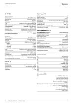
Number 8 Galvanic separation Yes Maximum cable length < 1000 m Operating mode Selectable for each input: high-active or low-active Factory setting high-active Voltage range (high) DC 12…30 V Voltage range (low) DC 0…2 V Max. current per channel (at AC/DC 30 V) 8 mA Connection plug-in terminal (1-1) (2-2) (3-3) … (8-8) Interface/protocol Operating mode Baud rate Cable length Cable Cable recommended Cable alternatively Connection Connection type Terminating resistor Device address, internal BMS bus RS-485/BMS internal Master/slave (master)* 9.6 kBaud ≤ 1200 m Shielded, one end of shield connected...
Open the catalog to page 8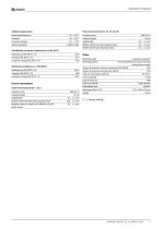
Ambient temperatures Push-wire terminal B (X1, X2, X3, X4, X5) Operating temperature Transport Long-term storage Operating altitude Conductor sizes Stripping length rigid/flexible flexible with ferrule without plastic sleeve flexible with ferrule with plastic sleeve Classification of climatic conditions acc. to IEC 60721 3M11 Device connections Push-wire terminal A (A1/+, A2/-) flexible with ferrule with/without plastic sleeve 0.25_2.5 mm2 Multiple conductor, flexible with TWIN ferrule with 0.5_1.5 mm2 plastic sleeve Operating mode Continuous operation Mounting position Front-orientated, air...
Open the catalog to page 9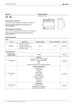
Dimension diagram The full text of the EU Declaration of Conformity is available via: UKCA Declaration of Conformity The full text of the UKCA Declaration of Conformity is available via: Ordering information
Open the catalog to page 10
Bender GmbH & Co. KG Londorfer Straße 65 35305 Grünberg Germany Tel.: +49 6401 807-0 [email protected] www.bender.de © Bender GmbH & Co. KG, Germany Subject to change! The specified standards take into account the edition valid until 07.2025 unless otherwise indicated.
Open the catalog to page 12All BENDER GmbH & Co KG catalogs and technical brochures
 CD25000
4 Pages
 CD14400
4 Pages
 CD1000
4 Pages
 AUR381Z
4 Pages
 AN110
AN1104 Pages
 AGH575S-6
4 Pages
 CD1000-2
4 Pages
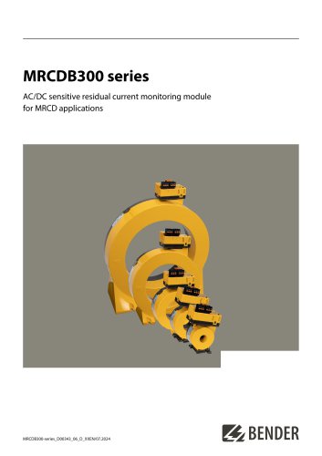 MRCDB300 series
12 Pages
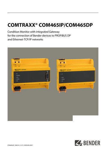 COMTRAXX® COM465IP/COM465DP
10 Pages
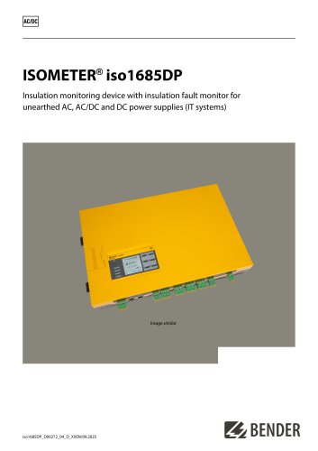 ISOMETER® iso1685DP
10 Pages
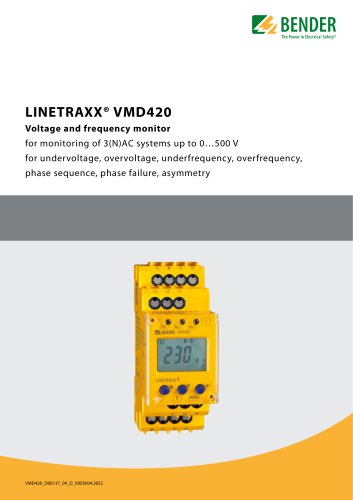 LINETRAXX® VMD420
6 Pages
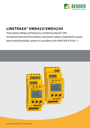 LINETRAXX® VMD423/VMD423H
6 Pages
 ISOMETER® iso685(W)-x-B
12 Pages
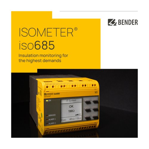 ISOMETER® iso685
12 Pages
 UNIMET® 810ST
4 Pages
 UNIMET® 610ST
4 Pages
 UNIMET® 400ST
4 Pages
 UNIMET® 300ST
4 Pages
 AN111
AN1114 Pages
 AN450
AN4504 Pages
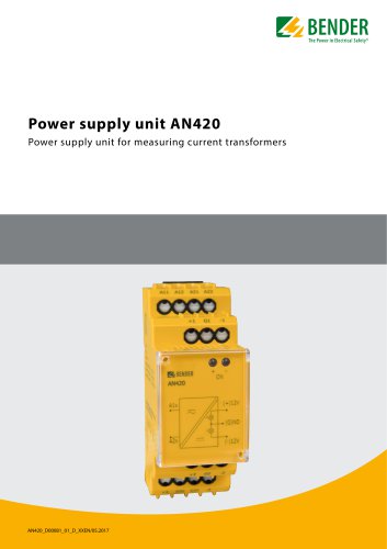 AN420
AN4204 Pages
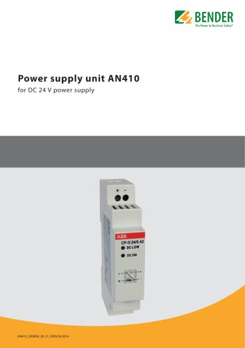 AN410
AN4104 Pages
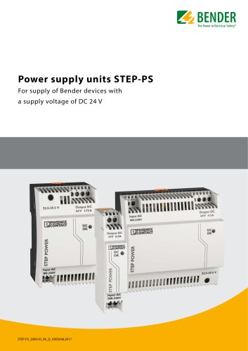 STEP-PS
8 Pages
 CTBC17 series
8 Pages
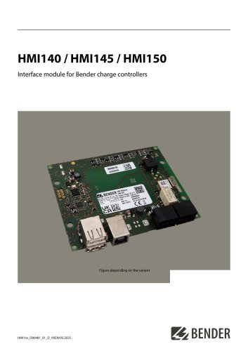 HMI140 / HMI145 / HMI150
6 Pages
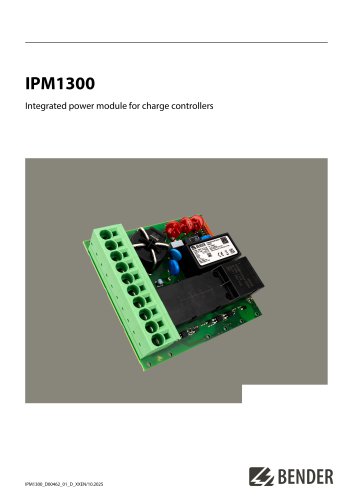 IPM1300
8 Pages
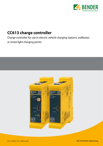 CC613
CC6136 Pages
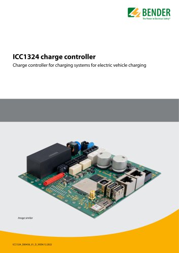 ICC1324
8 Pages
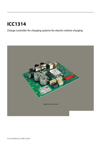 ICC1314
8 Pages
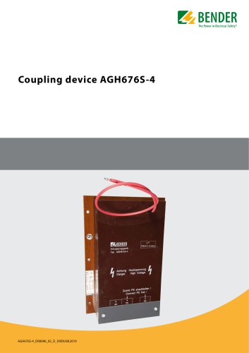 AGH676S-4
4 Pages
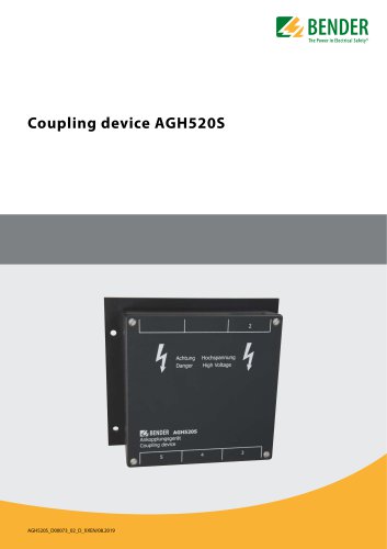
 AGH520S
4 Pages
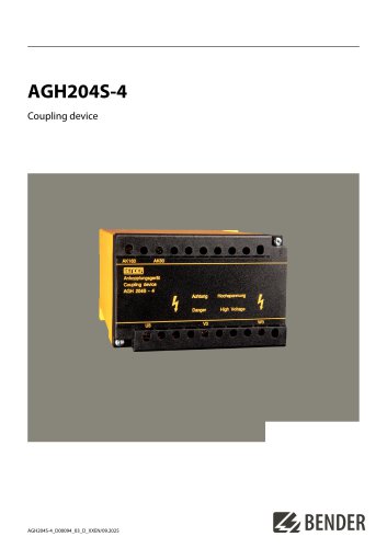 AGH204S-4
4 Pages
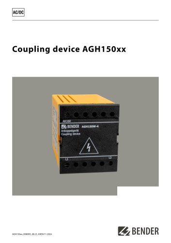 AGH150xx
4 Pages
 LINETRAXX® WF… series
4 Pages
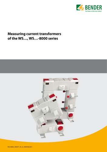 WS…, WS…-8000 series
4 Pages
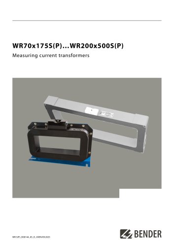 WR70x175S(P)…WR200x500S(P)
4 Pages
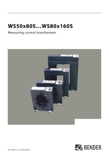 WS50x80S…WS80x160S
4 Pages
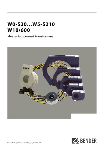 W0-S20…W5-S210 W10/600
4 Pages
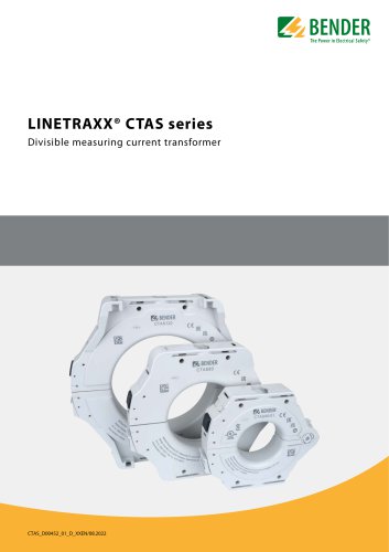 LINETRAXX® CTAS series
8 Pages
 LINETRAXX® CTBS25
4 Pages
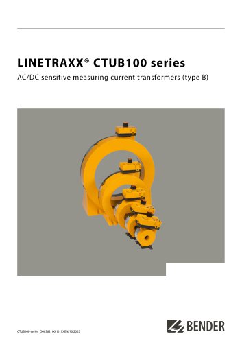 LINETRAXX® CTUB100 series
10 Pages
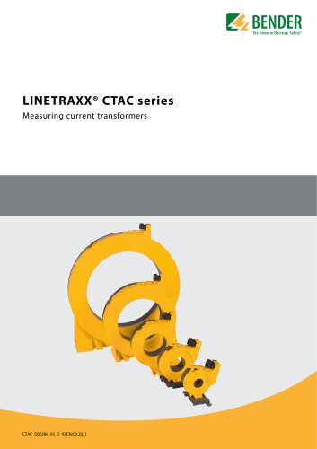 LINETRAXX® CTAC series
6 Pages
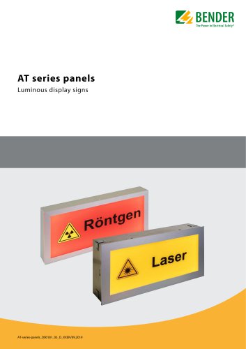 AT series
6 Pages
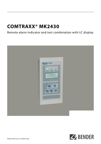 COMTRAXX® MK2430
6 Pages
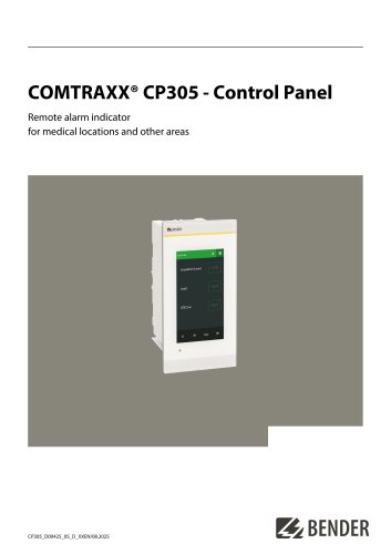 COMTRAXX® CP305
12 Pages
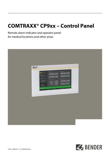 COMTRAXX® CP9xx
8 Pages
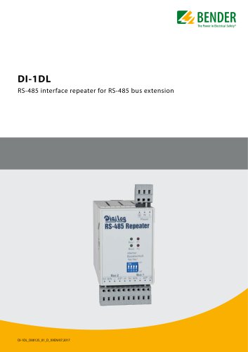 DI-1DL
4 Pages
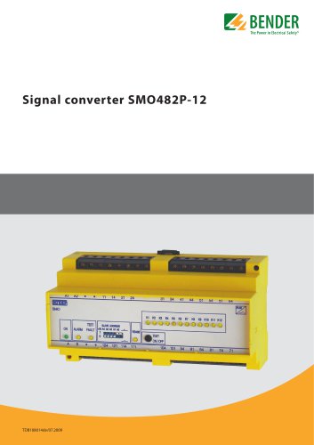 SMO482P-12
4 Pages
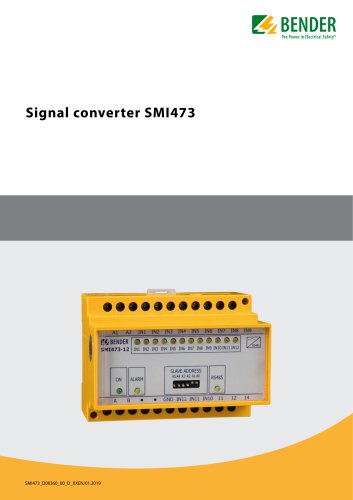 Signal converter SMI473
4 Pages
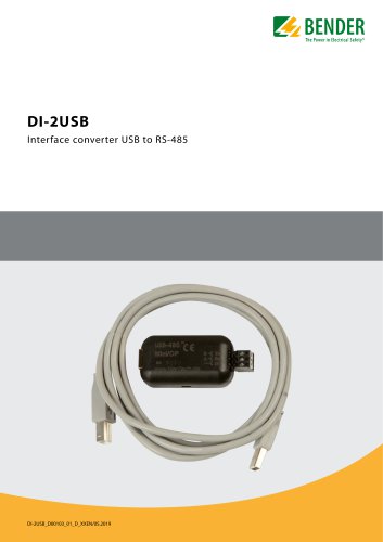 DI-2USB
4 Pages
 COMTRAXX® COM463BC
7 Pages
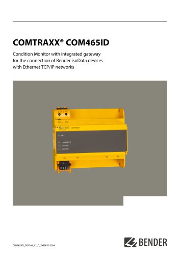 COMTRAXX® COM465ID
8 Pages
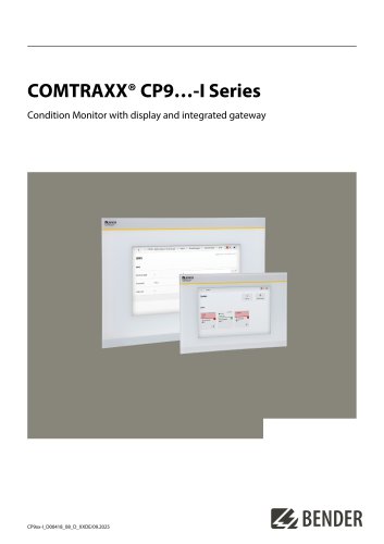 COMTRAXX® CP9…-I Series
10 Pages
 POWERSCOUT®
8 Pages
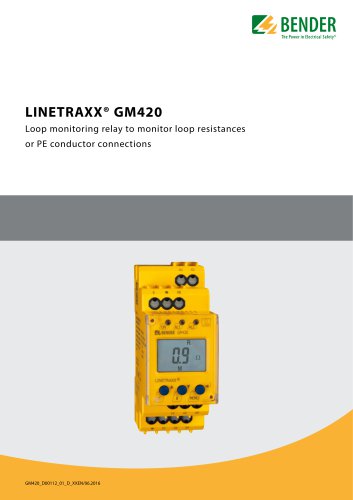 LINETRAXX® GM420
6 Pages
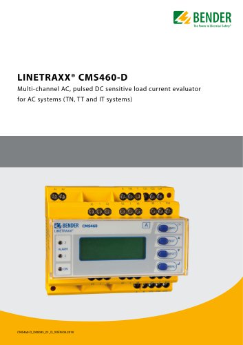 LINETRAXX® CMS460-D
10 Pages
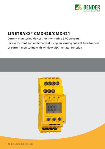 LINETRAXX® CMD420/CMD421
6 Pages
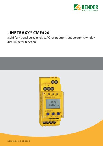 LINETRAXX® CME420
6 Pages
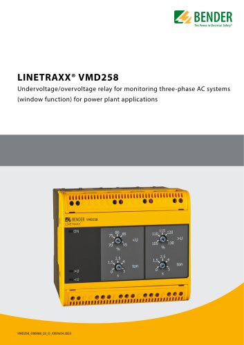 LINETRAXX® VMD258
6 Pages
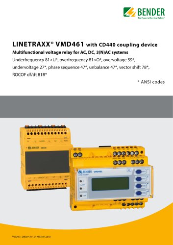 LINETRAXX® VMD461
10 Pages
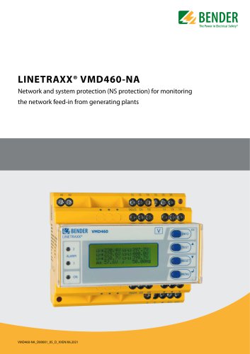 LINETRAXX® VMD460-NA
8 Pages
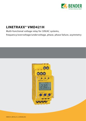 LINETRAXX® VMD421H
6 Pages
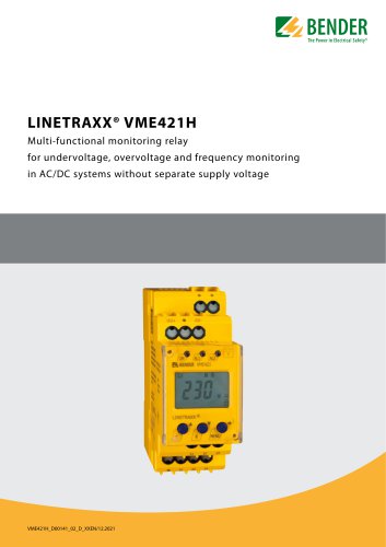 LINETRAXX® VME421H
6 Pages
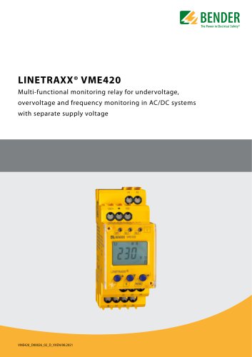 LINETRAXX® VME420
6 Pages
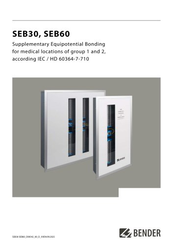 SEB30, SEB60
8 Pages
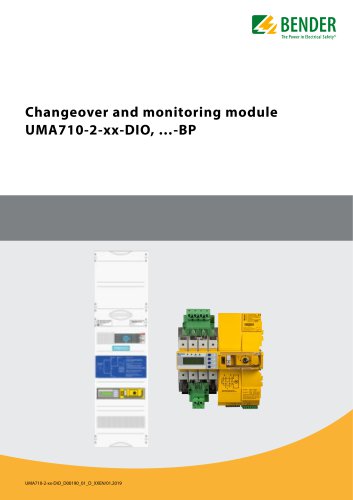 UMA710-2-xx-DIO, …-BP
6 Pages
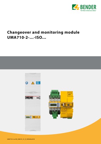 UMA710-2-…-ISO…
6 Pages
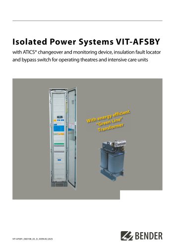 VIT-AFSBY
6 Pages
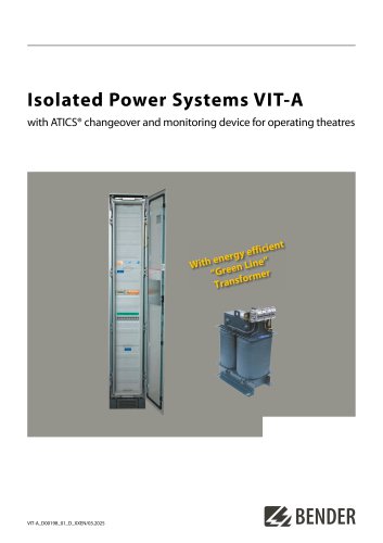 VIT-A
VIT-A6 Pages
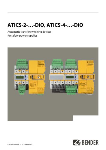 ATICS-2-…-DIO, ATICS-4-…-DIO
8 Pages
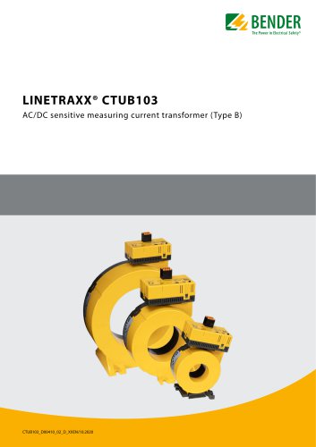 LINETRAXX® CTUB103
6 Pages
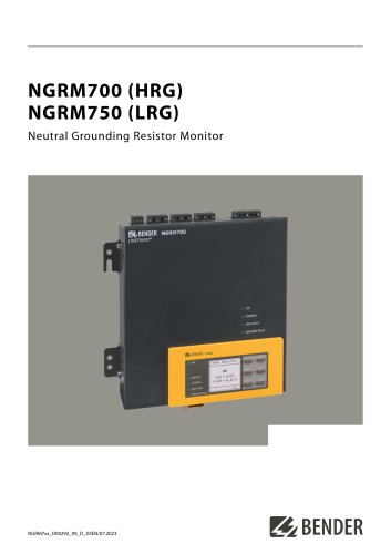 NGRM700 (HRG)/NGRM750 (LRG)
12 Pages
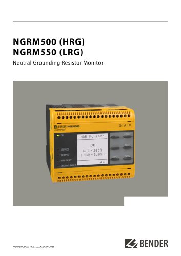
 NGRM500 (HRG)/NGRM550 (LRG)
12 Pages
 RDC125-5S
12 Pages
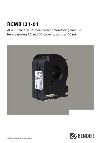 RCMB131-01
4 Pages
 RDC121
7 Pages
 RCMB123
7 Pages
 Residual current sensors
2 Pages
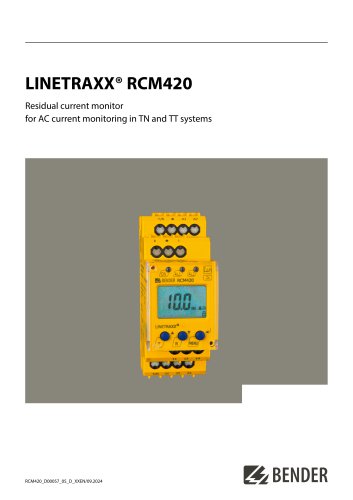 LINETRAXX® RCM420
6 Pages
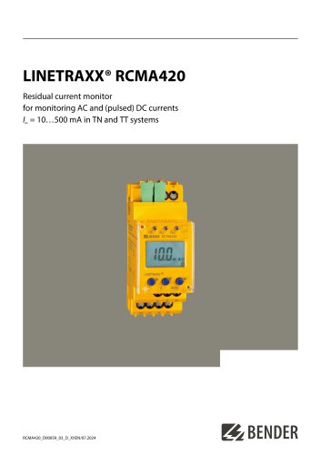 LINETRAXX® RCMA420
6 Pages
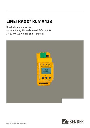 LINETRAXX® RCMA423
6 Pages
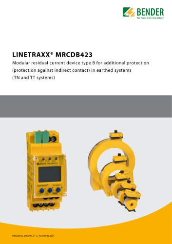 LINETRAXX® MRCDB423
6 Pages
 RDC104-4
6 Pages
 RCMB104
6 Pages
 LINETRAXX® RCMB330
4 Pages
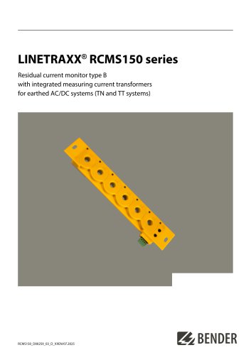 LINETRAXX® RCMS150 series
8 Pages
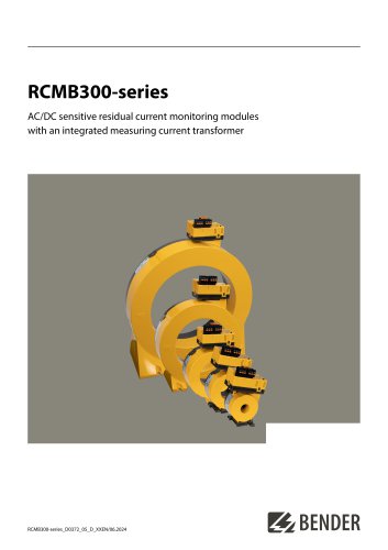 RCMB300-series
12 Pages
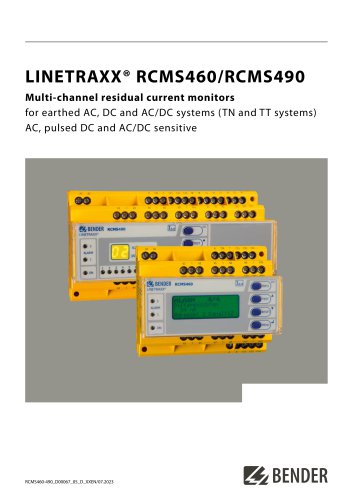 LINETRAXX® RCMS460/RCMS490
14 Pages
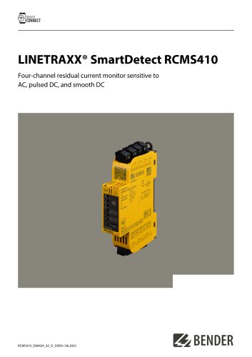
 LINETRAXX® SmartDetect RCMS410
10 Pages
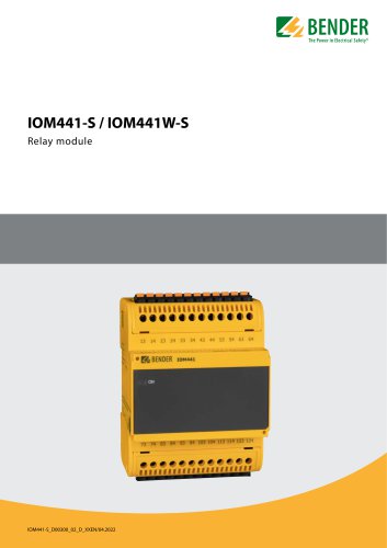 IOM441-S / IOM441W-S
4 Pages
 EDS3090/-91/-92/-96
14 Pages
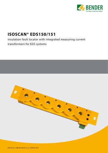 ISOSCAN® EDS150/151
6 Pages
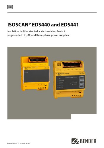 ISOSCAN® EDS440/EDS441
16 Pages
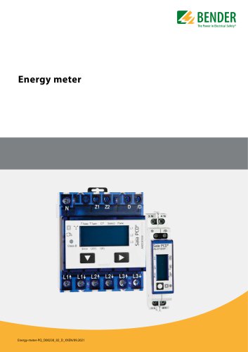 Energy meter
6 Pages
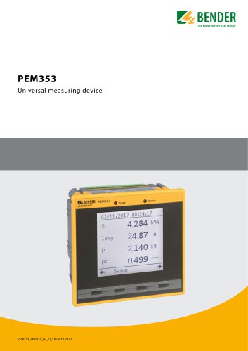 PEM353
8 Pages
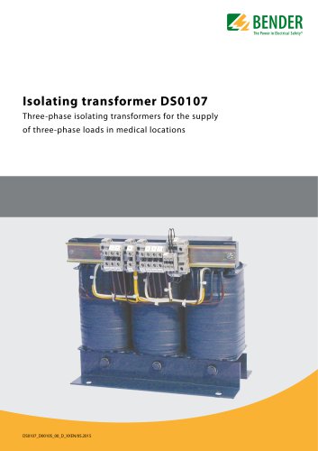 DS0107
6 Pages
 ESL0107
4 Pages
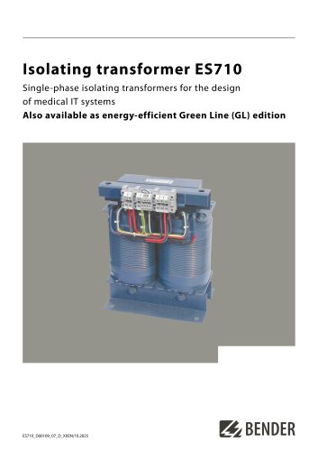 ES710
ES7108 Pages
 7204/7220/9604/9620
4 Pages
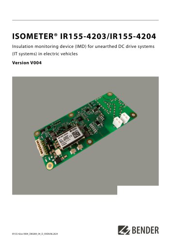
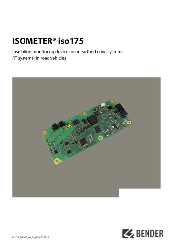 ISOMETER® iso175
8 Pages
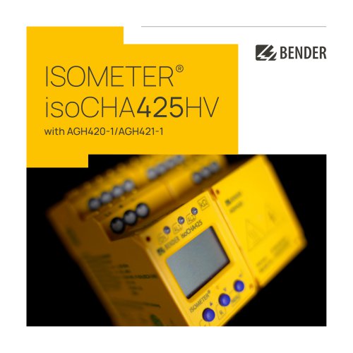
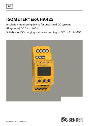 ISOMETER® isoCHA425
8 Pages
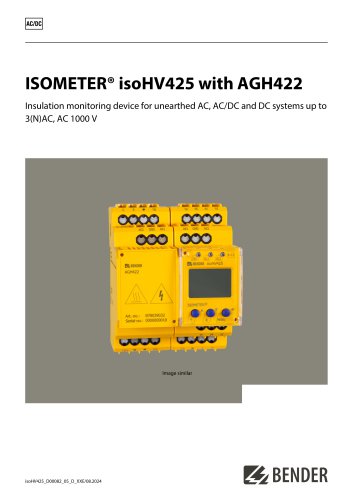 ISOMETER® isoHV425 with AGH422
10 Pages
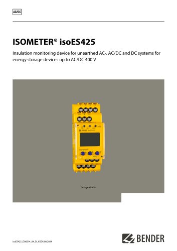 ISOMETER® isoES425
8 Pages
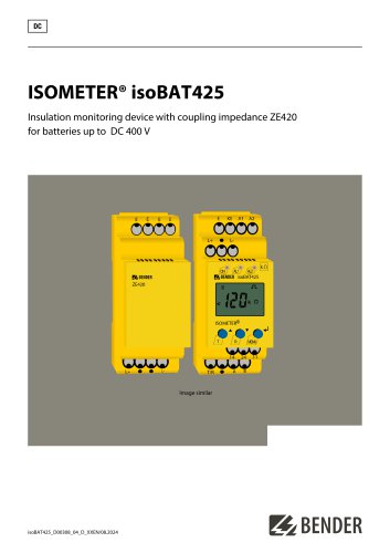 ISOMETER® isoBAT425
8 Pages
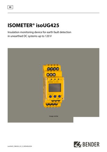 ISOMETER® isoUG425
6 Pages
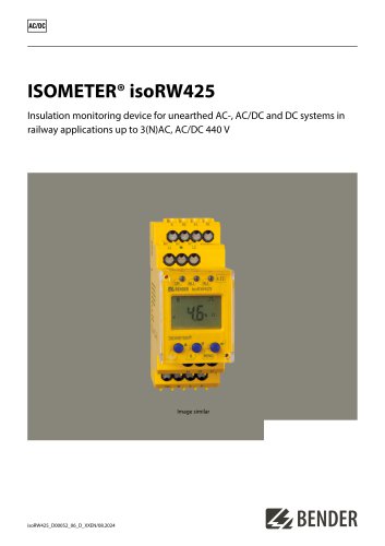 ISOMETER® isoRW425
8 Pages
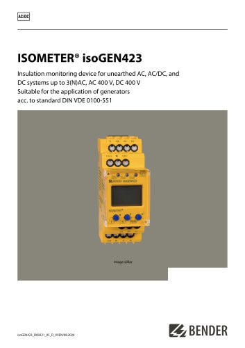 ISOMETER® isoGEN423
6 Pages
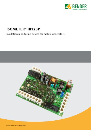 ISOMETER® IR123P
4 Pages
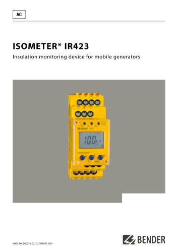 ISOMETER® IR423
6 Pages
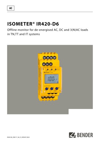 ISOMETER® IR420-D6
6 Pages
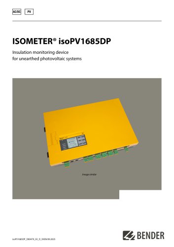 ISOMETER® isoPV1685DP
10 Pages
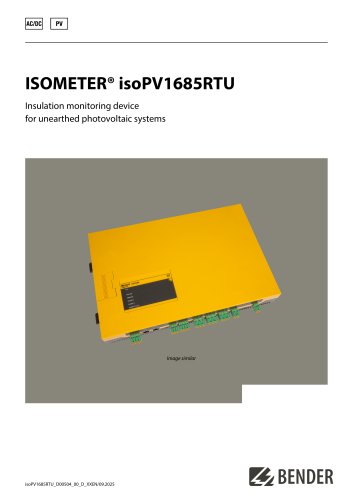 ISOMETER® isoPV1685RTU
8 Pages
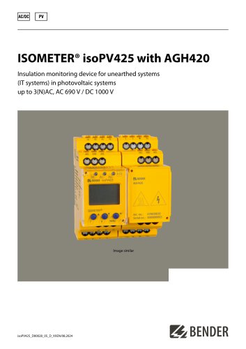
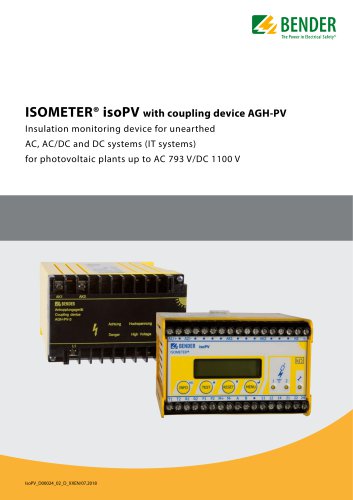 ISOMETER® isoPV
8 Pages
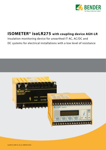 ISOMETER® isoLR275
6 Pages
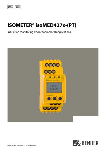 ISOMETER® isoMED427x-(PT)
6 Pages
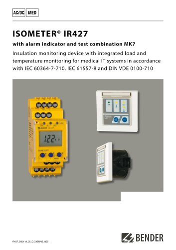 ISOMETER® IR427
8 Pages
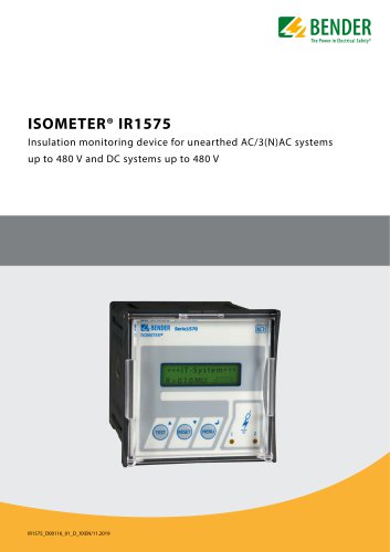 ISOMETER® IR1575
6 Pages
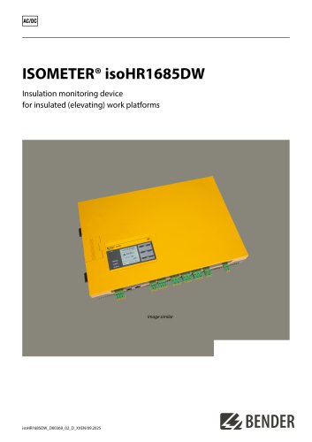 ISOMETER® isoHR1685DW
10 Pages
 ISOMETER® IR425-D4
6 Pages
 ISOMETER® IR420-D4
6 Pages
 ISOMETER® iso415R
2 Pages
 ISOMETER® IRDH275BM-7
6 Pages
 ISOMETER® isoRW685W-D-B
10 Pages
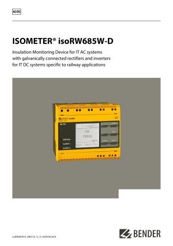 ISOMETER® isoRW685W-D
10 Pages
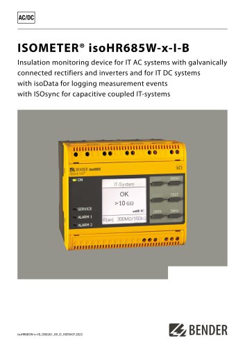 ISOMETER® isoHR685W-x-I-B
10 Pages
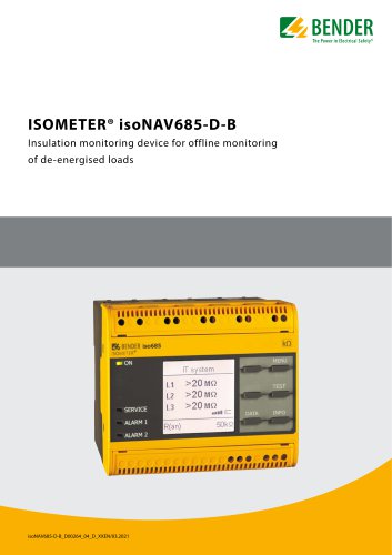 ISOMETER® isoNAV685-D-B
8 Pages
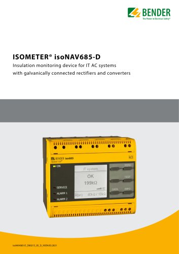 ISOMETER® isoNAV685-D
8 Pages
 AGH520S
4 Pages
 NGRM500 et NGRM550
12 Pages
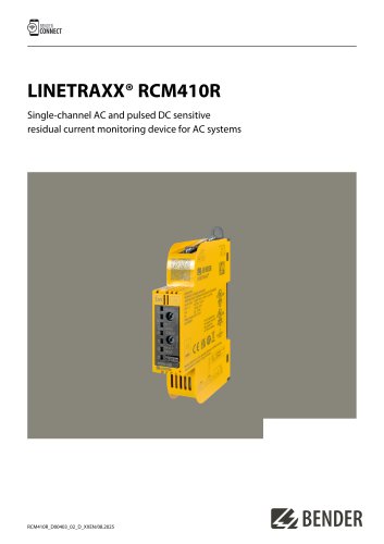 RCM410R
8 Pages
 RCMS410
10 Pages
 RCMS425-D
10 Pages
 EDGE500
12 Pages
 Iso415R
4 Pages
 Iso685-x-B
12 Pages
 Iso685-x-P
14 Pages
 Iso685-x
12 Pages
 Data Centers
16 Pages
 RCMB104
6 Pages
 LINETRAXX® RCMS460 / RCMS490
14 Pages
 LINETRAXX® SmartDetect RCMS410
10 Pages
 Main Catalogue
486 Pages

- Display module
- AC/DC power supply
- BENDER transformer
- Measuring device
- BENDER dry transformer
- CE power supply
- Cloud-based software
- Junction block
- Single-output power supply
- Power supply for industrial applications
- Portable tester
- Monitoring software solution
- Communication gateway
- LED display panel
- BENDER current transformer
- BENDER IEC transformer
- Power supply with overload protection
- Compact power supply