- Catalogs
- BELTRAME CSE
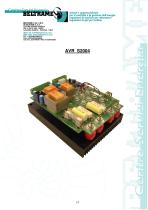
- S2004
S2004
1 /7Pages

S2004
1 /7Pages
Catalog excerpts
CENTRO SERVIZI ENERCIA CALLIERA VENETA - PADOVA - ITALY per H controllo e la gestione dell energia regolatori di tensione per alternatori regolatori di giri per turbine
Open the catalog to page 1
DESCRIPTION _______________________________________________________ 3 TECHNICAL DESCRIPTION ___________________________________________ 4 ELECTRONIC CARD CONNECTIONS ___________________________________ 5 ELECTRIC CONNECTION ________________________________________________ 6
Open the catalog to page 2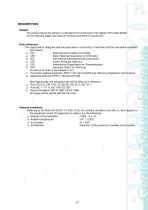
The present document allows to understand the functioning of the digital AVR model S2004. On the following pages are listed all functions and electric connexions. Rule references The supply will be designed and manufactured in conformity to the Rules and the here below indicated □ CEI Electrotechnical Italian Committee □ UNI Italian National Association of Unification □ IEC International Electrotechnical Commission □ VDI Verein Deutsche Ingenieur □ ISO International Organization for Standardization □ DIN Deutsche Institut fur Normung As well as all rules of law related to the: □ Prevention against...
Open the catalog to page 3
TECHNICAL DESCRIPTION Thanks to more than thirty years of experience gained on the field of tension regulators, BELTRAME C.S.E. has realized a model of low power static exciter, that can be used on Brushless generators of new or old manufacturing and on exciting dynamos. It uses the most sophisticated technologies available from the nowadays electronic and it allows the supply to exciting circuits with nominal tension values up to 200 Volt, so that it can be used on almost all type of machines present in the market. It is equipped with an adequate internal protection against a prolonged overcharge...
Open the catalog to page 4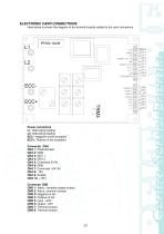
ELECTRONIC CARD CONNECTIONS Here below is shown the diagram of the terminal boards related to the card connexions. Power connectors ECC+: Positive of the excitation CNB 1: Alarm, normally closed contact CNB 2: Alarm, common contact
Open the catalog to page 5
ELECTRIC CONNECTION Connect the supply between terminals L1 and L2 by respected phases. The excitation winding ha be connected between terminal “ECC-“ and “ECC+”. The command signal could be could be a signal 0÷10V, by proceeding with a connection between pin 5 and 6 of CNA or a signal -5V÷5V with a connection between pin 6 and 7 of CNA. In order to enable the first input (0÷10V) you have to connect pin 7 with pin 8 of connector CNA. The second input can be enabled (-5V÷5V) by connecting pin 5 with pin 10 of connector CNA. In both cases it is necessary to short-circuit pin 3 and 4 of connector...
Open the catalog to page 6
INSTALLATION and ASSEMBLING This regulator must be installed inside the machine or inside the control and command panel, in order to protect it against the accidental contacts. It is advisable to position it in a place easily accessible and with a good circulation of clean and dry air. The four holes placed by its corners have to be used for its fixing.
Open the catalog to page 7All BELTRAME CSE catalogs and technical brochures
 S155
S1554 Pages
 S099
S0992 Pages
 S130 10A
4 Pages
 S2016
S20164 Pages
 S130
S1304 Pages
 S125
S1254 Pages
 S2013
S20134 Pages
 S2007
S20072 Pages
 S2022
S20224 Pages
 speed controller S2005
2 Pages
 speed controller S2007
2 Pages
 BM6.0M/BM6.0E
2 Pages
 DG5
DG54 Pages
 BM42E
BM42E2 Pages
 BM60M
BM60M2 Pages
 LPW2
LPW24 Pages
 DG164
DG1644 Pages
 DG4
DG44 Pages
 DG 184
4 Pages
 ARC2005
5 Pages
 ARC2000
10 Pages
 DG6
DG64 Pages
 DG182
DG1824 Pages
 DG162
DG1624 Pages
 DMW5E
DMW5E2 Pages
 Alternators DG5
4 Pages
 Diesel Generators DM5SE
2 Pages
 Diesel Generators DCM5E
2 Pages
 Diesel Generators DM5E
2 Pages
 Gasoline generators BM095
2 Pages
 Gasoline generators BT52E
2 Pages
 POWER FACTOR CONTROLLER
2 Pages
 AVR S160
2 Pages
 AVR S155
2 Pages
 AVR S130-10A
2 Pages
 AVR S130-25A
2 Pages
 AVR S125
2 Pages


Archived catalogs
 S2006
S20063 Pages
 S2006_2012
2 Pages
- Power generator
- Diesel generator set
- Industrial genset
- Three-phase generator set
- 50 Hz generator set
- Stationary genset
- Soundproof generator set
- Water-cooled generator set
- Single-phase generator set
- Open type generator set
- Mechanical fuel injection generator set
- Portable generator set
- Generator set with cover
- Speed controller
- Three-phase alternator
- Gas generator set
- Voltage regulator
- Gasoline engine generator set
- DC speed controller
- Industrial alternator